Simple Counter Circuit Diagram
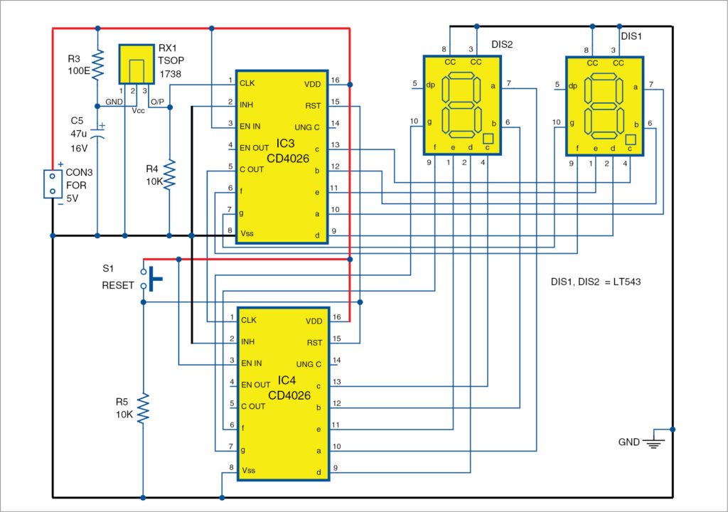
A couple of very simple frequency counter circuits are shown below and can be easily built by any electronic enthusiast for the intended purpose. Here is a simple 4026 manual digital counter circuit with reset and pause.
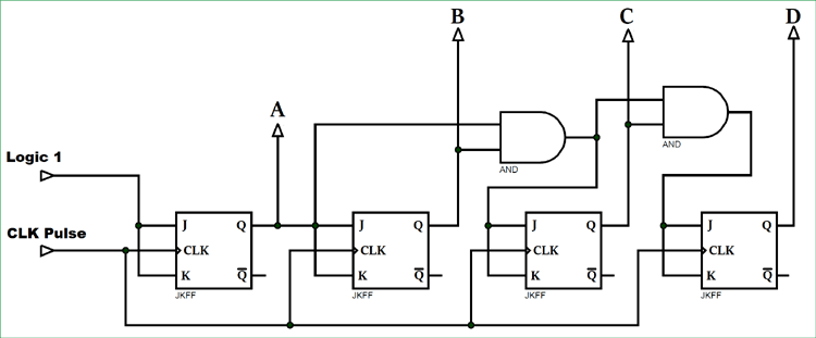
 Synchronous Counter And The 4 Bit Synchronous Counter
In this project we are going to design a simple object counter circuit without using any microcontroller.

Simple counter circuit diagram. This led to the development of a latch. This is 2 digit simple digital counter circuit using cd4026 as main parts can display with led 7 segment 0 99 number there is a reset button to restart. They count objects or products automatically and so reduce human efforts.
Counters are sequential circuits. This ensures a proper binary count sequence throughout the overall counter circuits range. The counters four outputs are designated by the letter symbol q with a numeric subscript equal to the binary weight of the corresponding bit in the bcd counter circuits code.
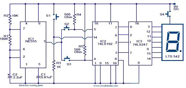
Object counters or product counters are important applications used in industries shopping malls etc. Simple 2 digit auto manual counter september 18 2014 by engineers garage as shown in circuit diagram figure the major components of circuit are ic555 decade counter cum display driver cd4026 and common cathode type 7 segment display. So we had to find a way to remember the previous state.
A latch is a simple circuit that latches on or stores 1 or 0. By definition a circuit whose present output depends on present input past output is called a sequential circuit. The working principle as circuit in figure 1.
So for example q a q b q c and q dthe 74ls90 counting sequence is triggered on the negative going edge of the clock signal that is when the clock signal clk goes from logic 1 high to logic 0 low. It can be applied to for example counting products counting people into the library and more. The important lesson in this question is that synchronous counter circuits with more than two stages need to be configured in such a way that all higher order stages are disabled with the terminal count of the lowest order stage is inactive.
This counter circuit applicable for order to count certain events such as people counter product counter etc. Circuit uses digital counter ic 4026 and 7 segment display.
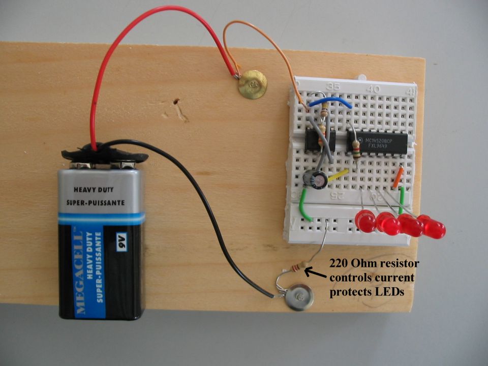
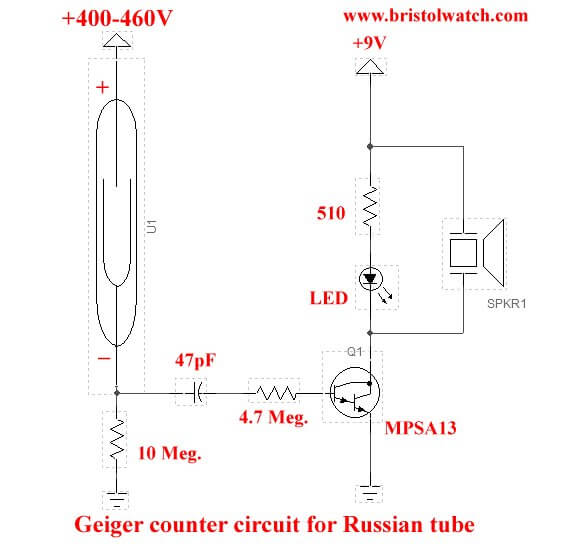
 Simple Geiger Counter Tutorials Robotshop Community
 Simple Program Counter
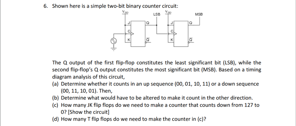 Solved Shown Here Is A Simple Two Bit Binary Counter Circ
 Hello Friends Today A Two Digit Counter With Count And
 Simple Low Cost Visitor Counter Detailed Project Available
 Laser Interference Pattern Enumerator
 Counter Circuit Diagram Simple Electronics Hobby Project For
 Digital Stopwatch Circuit Electronics Circuit Circuit

 Simple 2 Digit Auto Manual Counter Circuit Electronic
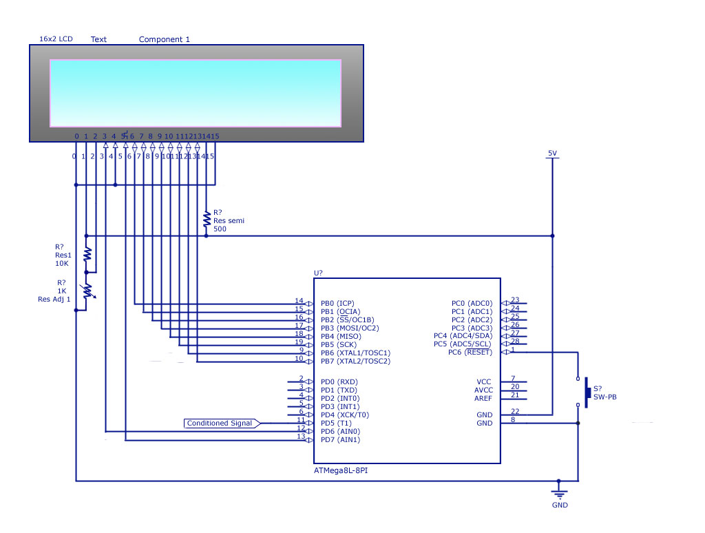
 Creating A Simple Counter Circuit Using A Pic Microcontroller With Assembly Language Programming
 Synchronous Counter Definition Working Truth Table Design
 Synchronous Counter And The 4 Bit Synchronous Counter

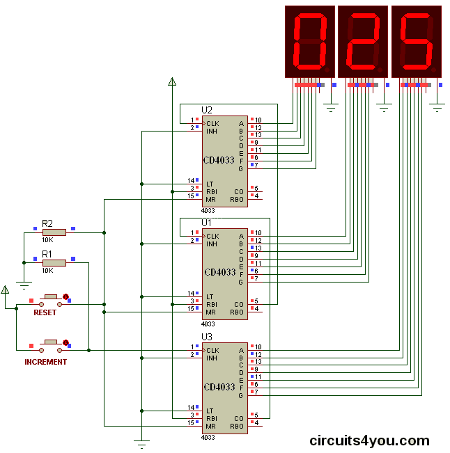 Three Digit Object Counter Circuits4you Com
 Bcd Counter
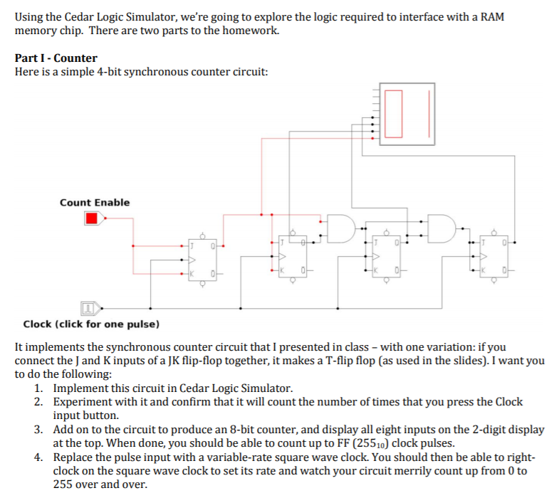 Using The Cedar Logic Simulator We Re Going To Ex
 Simple Program Counter
 4 A Simple Counter Circuit Built With The Rtlib Simulation
 Counters Digital Circuits Worksheets
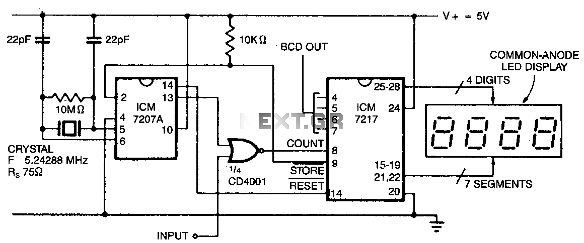
 Frequency Counter Circuit 555 Simple 3 1 2 Digit Frequency
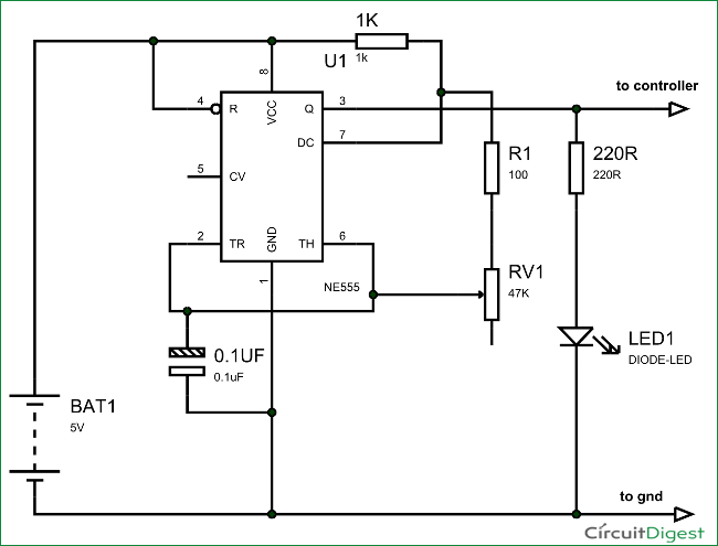
Simple Rpm Counter Using Ic555 Circuit Diagram
0 Response to "Simple Counter Circuit Diagram"
Post a Comment