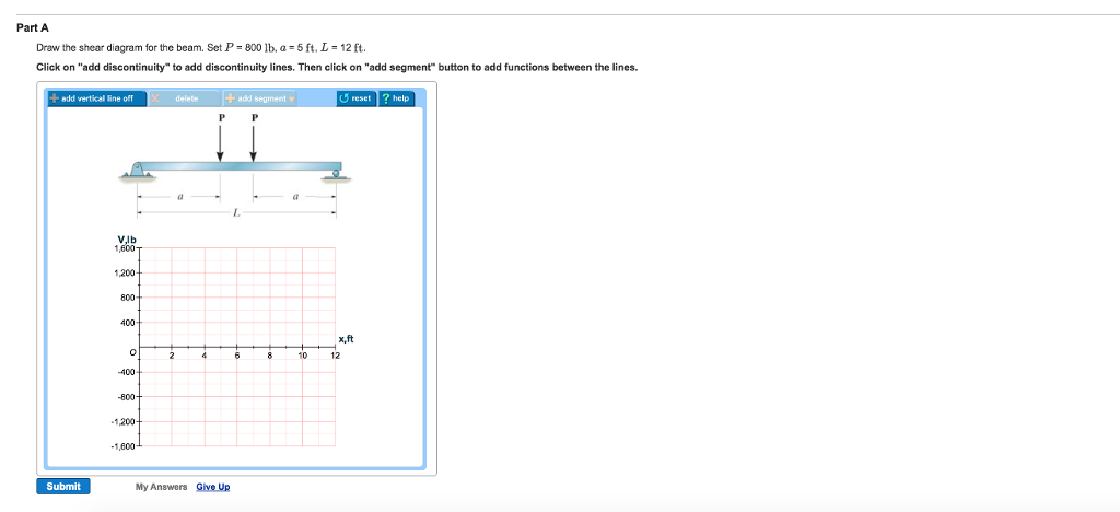
Draw The Shear Diagram For The Beam Set P 800 Lb A 5 Ft L 12 Ft
Set p 800 lb a 5 ft l 12 ft click on add discontinuity to add discontinuity lines. B set p 600lb a 5ft b7ft.
Solution
Moment diagram at 1238.
Draw the shear diagram for the beam set p 800 lb a 5 ft l 12 ft. Draw the shear and moment diagrams for the beam a in terms of the parameters shown. Part a draw the shear diagram for the beam. B set p 800 lb a 5 ft l 12 ft.
Wx 36012 or w 30x lbft. The distributed load applies a load at every single point that it covers so infinitely many shear decreases over any horizontal distance. For this problem establish the x axis with the origin at the left side of the beam and obtain the internal shear and moment as a function of x.
Establish the m and x axes and plot the value of the moment at each end. When vbc 0 2400 800x 0 thus x 3 ft or vbc 0 at 1 ft from b. The next force is 10 lb.
A 5 ft l 12 ft. The slope of the shear diagram over the interval 2l x 3l is zero since wx 0. Drawing shear and moment diagrams example mechanics of materials and statics.
In other words the line will be sloped. Chapter 09 solution manual mechanics of materials chapter 05 solution manual mechanics of materials chapter 07 solution manual mechanics of materials chapter 04. The shear diagram is now at 1167 lb on the positive side.
1 answer to draw the shear and moment diagrams for the beam a in terms of the parameters shown. Draw the shear and moment diagrams for the beam a in terms of the parameters shown. Vbc 2400 800x is linear.
At x 6 ft vbc 2400 lb. Shear force and bending moment diagram for simply supported beam with udl. B set p 800 lb.
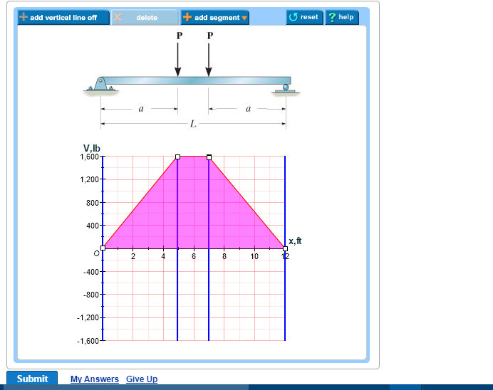
The resulting shear diagram matches the shear at the right end determined from the equilibrium equations. To draw the shear diagram. Add vertical line off delete add segment vlb 1600t 1200 800 400 6 810 submit my answers give up.
Use the results to plot the shear and moment diagrams. 800 lb of shear force is uniformly distributed along segment ab. M 1000x 5x3 lb ft answer because the loading is continuous the beam does not have to be divided into segment.
Then click on add segment button to add functions between the lines. The shear line will step down from 1167 lb to 167 lb. At x 2 ft vbc 800 lb.
Shear Forces And Bending Moments
 Hibbeler Statics 12 Ed Cap 7 2
 Determine The Normal Shear Force And Bending Moment At C And D
Ch 7 Solution Manual Engineering Mechanics Statics
Chapter 06 Solution Manual Mechanics Of Materials Mom
 Chapter 06 Solution Manual Mechanics Of Materials Mom
Solution

 Solved Part A Draw The Shear Diagram For The Beam Set P
 Hibbeler Statics Solution Chapter 7 1
Solution
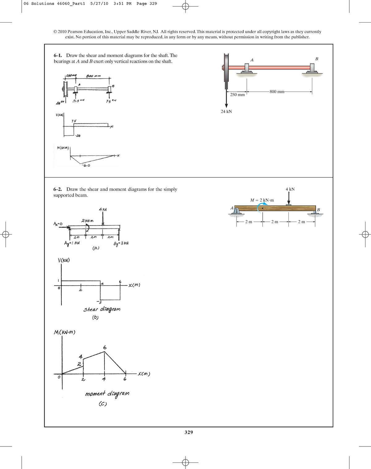
329 6 1 Draw The Shear And Moment Diagrams For The Shaft
Untitled
 Hibbeler Statics Solution Chapter 7 1
Solution
Untitled
 Determine The Normal Force Shear Force And Moment At Point C
329 6 1 Draw The Shear And Moment Diagrams For The Shaft
 Solved Plz Help In This Question Part A Draw The Shear D
329 6 1 Draw The Shear And Moment Diagrams For The Shaft
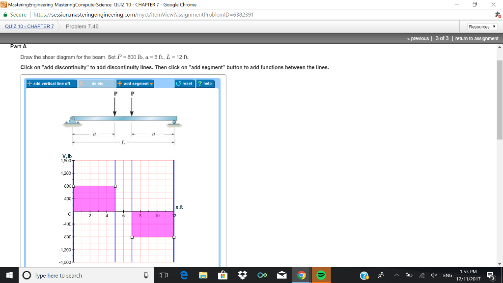 Solved Asteringengineering Masteringcomputerscience Ouiz
Solution
Chapter 06 Solution Manual Mechanics Of Materials Mom
Mechanics Of Materials Chapter 5 Stresses In Beams
329 6 1 Draw The Shear And Moment Diagrams For The Shaft
Hibbeler Chapter 6 Part 1 463 486 Qxd

329 6 1 Draw The Shear And Moment Diagrams For The Shaft
Hibbeler Chapter 6 Part 1 463 486 Qxd
0 Response to "Draw The Shear Diagram For The Beam Set P 800 Lb A 5 Ft L 12 Ft"
Post a Comment