Lng Process Flow Diagram
Lng liquified natural gas terminal is a reception facility for unloading of cargo from lng tankers. Cascade process for natural gas liquefaction methane ethylene propane ng 32 12 c 14 bar 7.
 Process Flow Diagram Pfd N5 Electrical Schemes
Flow diagram for a typical lng plant.

Lng process flow diagram. Liquefied natural gas lng is natural gas that has been cooled to 260 f 162 c changing it from a gas into a liquid that is 1600th of its original volume. Block diagram of lng plant main process stages liquefaction process technologies examples from hammerfest lng plant. Typical dehydration scheme process flow water saturated natural gas water drier precooler hydrocarbon liquid regeneration gas.
2 3 hammerfest lng plant block flow diagram slug catcher inlet facilities metering co2 removal de hydration mercury removal natural gas liquefaction lpg. Of lng are provided at these terminals. A typical lng import terminal process flow diagram is shown in figure 5.
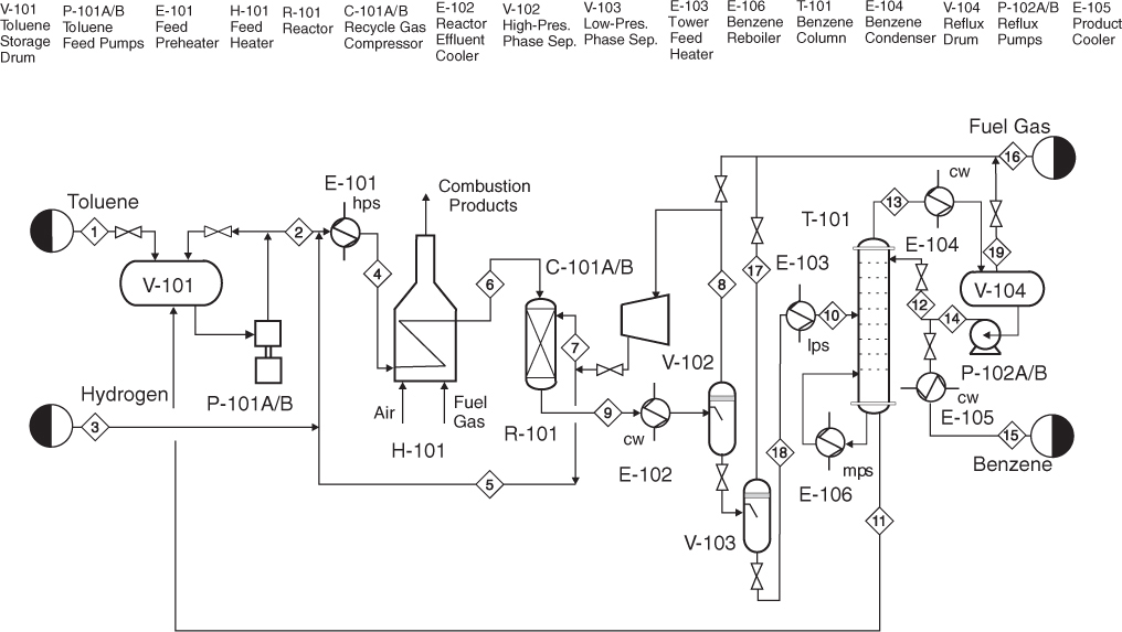
Liquefied natural gas lng for the 2014 spe roughneck camp chris caswell director lng and flng. Unloading arms cryogenic pipelines storage tanks low pressure pumps boil off gas bog compressors and re condensers. Dmr process has less equipment and allows a wider range of operating conditions than c3mr dmr process has more exploitable power than c3mr dmr has more specific capacity than c3mr process apci shell pwaga dmr process cost comparison refrigerant flow rate lng gabriel castaneda pe.
This purpose built ports are specially used for export and import of lng. Lng plant overview seminar with supplier association murmanshelf murmansk 15 may 2012 jostein pettersen. A variety of facilities for unloading regasification tanking metering etc.
Wikipedia the pfd example process flow diagram typical oil refinery was created using the conceptdraw pro diagramming and vector drawing software extended with the chemical and process engineering solution from the chemical and process engineering area of conceptdraw solution park. Lng plant overview jostein. Table of content part 1.
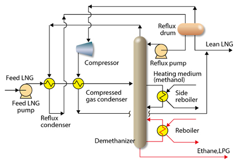
Process flow diagram q high temperature ambient q low temperature sub ambient condenser suction drum. Simplified lng plant block diagram end flash hhc extraction ch 4 n 2 fuel gas power heat. Lng j t expander bypass valve lng lng flash tank lng lng lng liquefied methane gas to sub cooler j t expander bypass valve compressor anti surge valve main cryogenic heat exchanger on site ccgt power plant provides electric power for compressor drives and steam for heating processes lng liquefaction process flow diagram.
Oil and gas production process flow diagram. The major equipment components of an lng import and regasification terminal are.
 Process Flow Diagram Natural Gas Schematic Wiring Diagram
Giignl Has Developed Following Fact Sheet To Provide Summary
 Lng Plant And Regasification Terminal Operations Sciencedirect
Lng Plant Overview
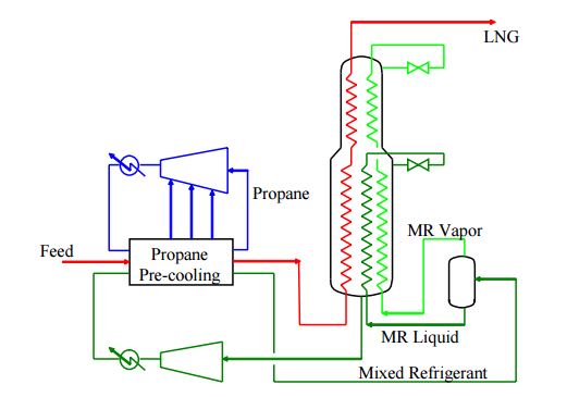
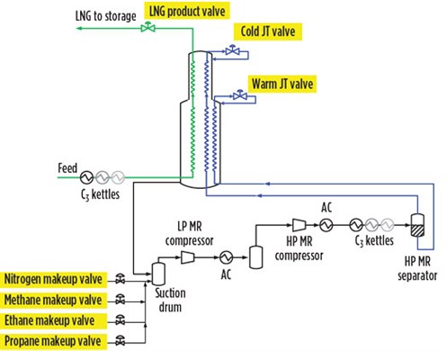
 Simplified Process Flow Diagram Of Ap X Lng Process
 Process Flow Diagram Pfd N5 Electrical Schemes

Lng Plant Overview
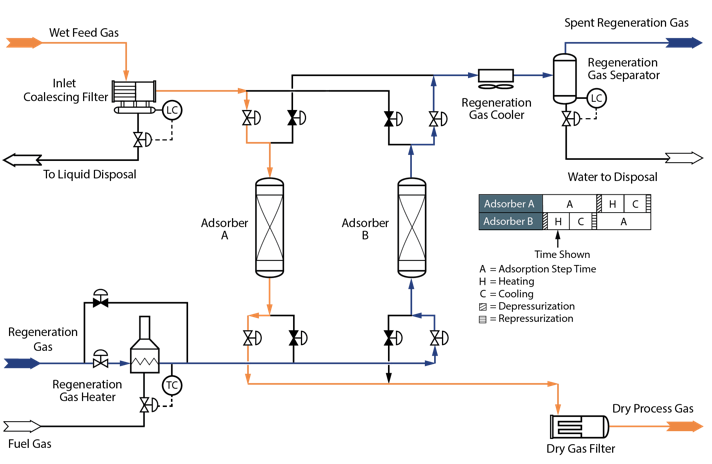
 Glycol Dehydration Wikipedia
Giignl Has Developed Following Fact Sheet To Provide Summary
Contamination Control For Lng Production
 Simplified Process Flow Diagram Of Ap X Lng Process
 Process Flow Diagram Lng Wiring Diagrams Folder
 Process Control And Automation Of Lng Plants And Import
Giignl Has Developed Following Fact Sheet To Provide Summary
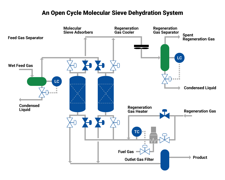 Dehydration And Organic Sulfur Removal Process Using
 Process Flow Diagram Lng Wiring Diagrams Folder
 Eia Report Part 2 Section13 Annex A1
 Process Flow Diagram Natural Gas Wiring Diagrams Pause
 Simplified Process Flow Diagram For The Operating Lng Train
 Simplified Lng Process Flow Download Scientific Diagram
 Process Flow Diagram Of The Methyldiethanolamine Process
Process Flow Diagram For The Double Stage Rankine Cycle

 Process Flow Diagram Lng Plant Wiring Diagram
0 Response to "Lng Process Flow Diagram"
Post a Comment