Hvac Wiring Diagram 101
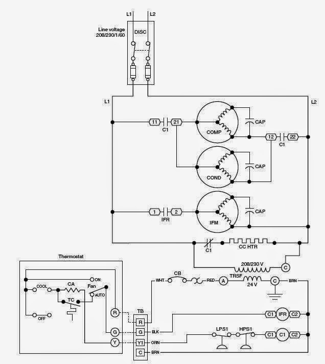
Thermostat terminal designations explanations. Figure 7 shows the system used for large industrial plants where most of the load consists of motors.
 Rv Hvac Wiring Diagram Catalogue Of Schemas
Most thermostats send commands to your hvac system heat or air conditioning via low voltage wires inside a command box.

Hvac wiring diagram 101. Each component should be placed and linked to other parts in particular way. This box enables you to set the temperature and configure heat or air conditioning programs depending on your habits and needs. From this point forward ladder dia.
Figure 6 is a diagram for a 480276 volt three phase four wire system. Hvac wiring diagram hvac wiring diagram hvac wiring diagram colors hvac wiring diagram pdf every electrical structure is made up of various diverse parts. It is a 480 volt delta three phase system.
Types of wiring diagrams there are three basic types of wiring diagrams used in the hvacr industrytoday. How to identify each wire for an hvac for a thermostat. 2 how to get the electrical wiring for air conditioning systems.
There are limitless topics to cover such as wind and solar energy active and passive solar heating and air conditioning hydrogen methane gardening aquaponics house design home engineering. Use our menu to the right to find helpful articles such as thermostat wiring diagrams low voltage circuits for hvac how to wire an air conditioner for control control board troubleshooting and thermostat troubleshooting. Usually the electrical wiring diagram of any hvac equipment can be acquired from the manufacturer of this equipment who provides the electrical wiring diagram in the users manual see fig1 or sometimes on the equipment itself see fig2.
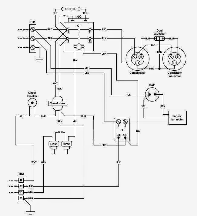
Fan coils accessory electric heaters wiring diagrams fig. A collection of hvac diagrams are available in the following printable diagrams to help you learn about the hvac systems. The first and most common is the ladder diagram so called because it looks like the symbols that are used to represent the components in the system have been placed on the rungs of a ladder.
Field installed heater model fb4c fe4afe5a fh4c fv4c fx4d fy5b pf4ma pf4mb label 1 kfceh0401n03a 1824 x 001 x 1925 1824 18192425 x 340816 101. Transformers are used to get 120 volt single phase circuits. The diagrams that we have collected in the following pictures below show basic structures of hvac systems.
Otherwise the structure wont function as it should be. This system serves hotels shopping centers etc.
 Hvac Contactor Wiring Diagram New Wiring Diagram For
 Hvac Wiring Diagrams Wiring Diagram Document Guide
 Hvac Wiring Diagrams 101 Schematics Online
 Hvac Wiring Schematics Wiring Diagram Document Guide


 The Modern Rules Of Hvac Wiring Diagrams Diagram Information
 Hvac Wiring Diagrams 101 Otorva Org


 Hvac Wiring Diagrams Troubleshooting Honeywell Thermostat
 Unique Residential Wiring 101 Thebrontes Co
 Hvac Schematic Diagram Wiring Diagram


 Basic Hvac Control Wiring Wiring Diagram Schematics
Hvac Electrical Diagrams Wiring Diagram Document Guide

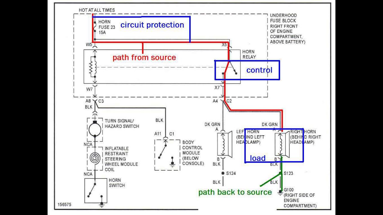 The Trainer 32 How To Read An Automotive Block Wiring Diagram

 Hvac Wiring Schematics Wiring Diagram Document Guide
 Hvac Wiring Guide Wiring Diagrams
0 Response to "Hvac Wiring Diagram 101"
Post a Comment