Timer Switch Circuit Diagram
How to make a timer circuit in which the switch is triggered and the light remains on around 30 sec and off automatically. Delay timer with relay i am looking to build a circuit that would control an output relay.
 Leviton Timer Switch Wiring Diagram Electric Bicycle
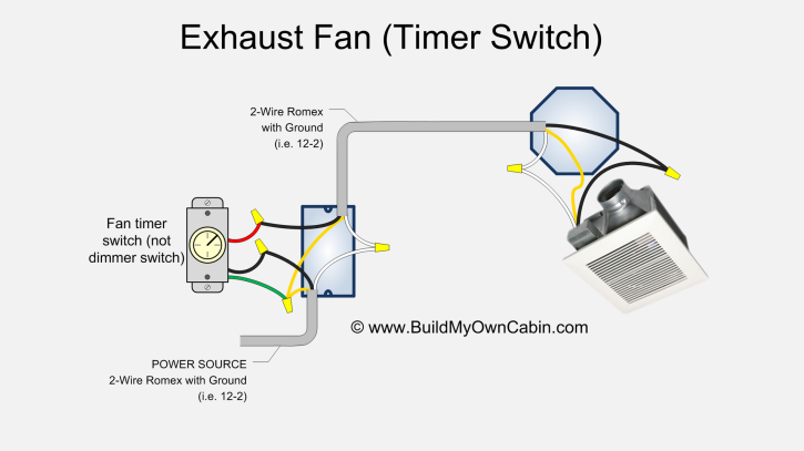
Attach timer switch wires.
Timer switch circuit diagram. We do not publish 3rd party spam comments track backs or links. Digital timer switch electrical wiring instructions comments posted here are open for quality discussion and participation. Check circuit diagrams for 1 minute timer 5 minute timer 10 minute timer and 15 minute timer.
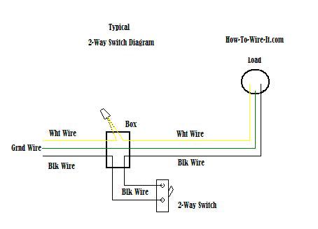
The source is at sw1 and 2 wire cable runs from there to the fixtures. The hot and neutral terminals on each fixture are spliced with a pigtail to the circuit wires which then continue on to the next light. The following circuit was requested by fastshack3.
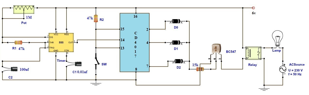
This circuit uses very basic components like 555 timer and 4017 counter. This diagram illustrates wiring for one switch to control 2 or more lights. These on off intervals can be adjusted by varying the 555 timer output and number of counter outputs.
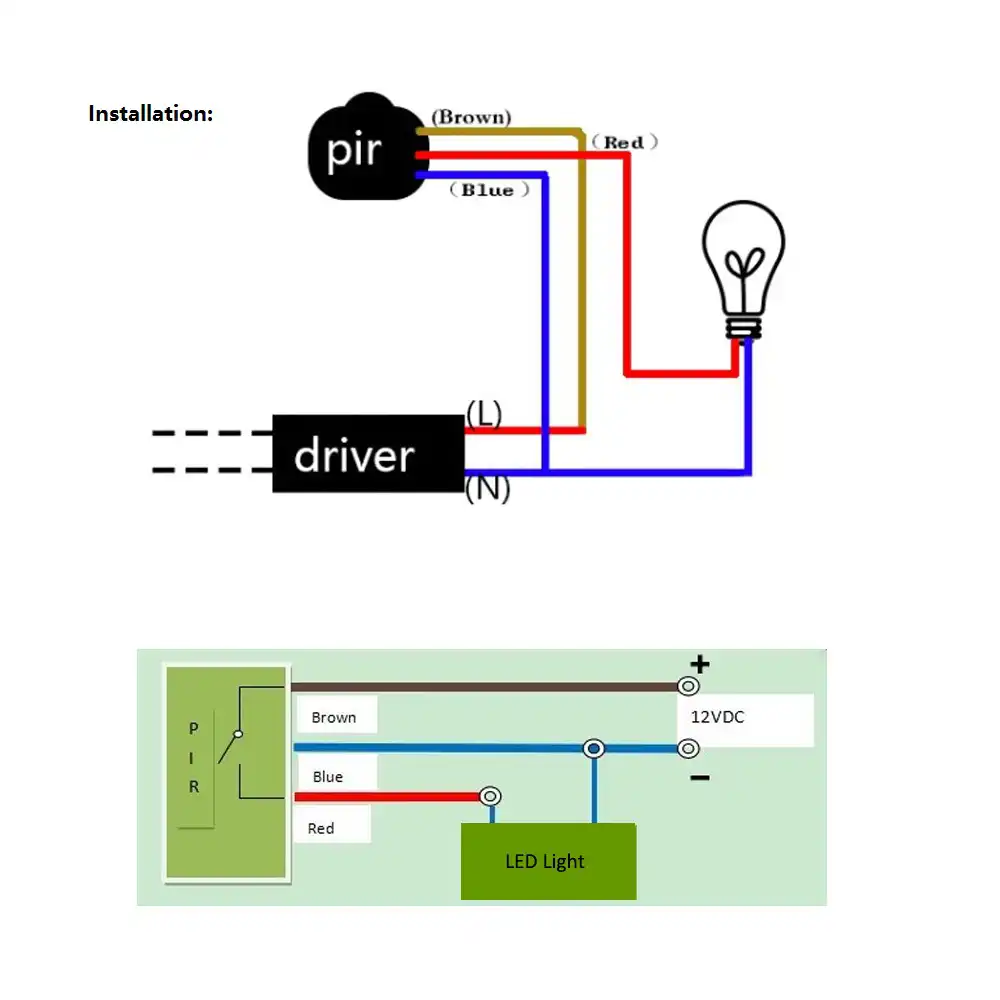
Adjustable on off timerusing 555 astable mode in this circuit a timer with cyclic on off operations is designed. On off switch circuit using a 555 timer. Attach the electrical wires to the timer switch following the instructions and wiring diagram that came with it.
Multiple light wiring diagram. This would be done in 12v and the sequence will be initiated by a manual switch. Let us discuss in detail about this circuit.
This circuit has many applications on places where it is necessary to activate and deactivate connect and disconnect an electrical or electronic device. It also has a potentiometer to adjust the time delay where you can increase of decrease the time delay by just rotating the potentiometer. Here with the help of the 555 timer ic we are eliminating the need of manually switching on or off the device.
If the ends on the wires are worn cut them off and strip them the insulation of the ends for a fresh connection. In this project we are going to design a simple time delay circuit using 555 timer icthis circuit consists of 2 switches one for start the delay time and other for reset. In this project we are using 555 timer ic to create various timer circuit like 1 min timer circuit 5 min timer circuit 10 min timer circuit and 15 min timer circuit.
With the help of this circuit you can turn on and off a device by simply touching the touch plates. The touch on and off switch circuit is built around a 555 timer by making use of the default properties of the pins of the 555 timer ic. We can easily calculate the resistor value for 5 minute 10 minute and 15 minute timer circuit.
This on off switch circuit using a 555 timer is simple useful and easy to implement. Attach wires to timer switch.

 Timer Switch Wiring Wiring Diagram Schematics
 Aerator Timer Switch Wiring Diagram Technical Diagrams


Switch Schematic Diagram Wiring Diagrams Show
 Timer Switch Wiring Diagram Wiring Diagram
 Timer Switches Wiring Diagrams Schematics Online


 Wire Diagram For Timer Switch Bookmark About Wiring Diagram

 Light Timer Wiring Diagram Wiring Diagram

 Three Way Switch Wiring Diagram With Timer Wiring Diagram T1
 Dc Timer Switch Wiring Diagram Wiring Diagram Schematics
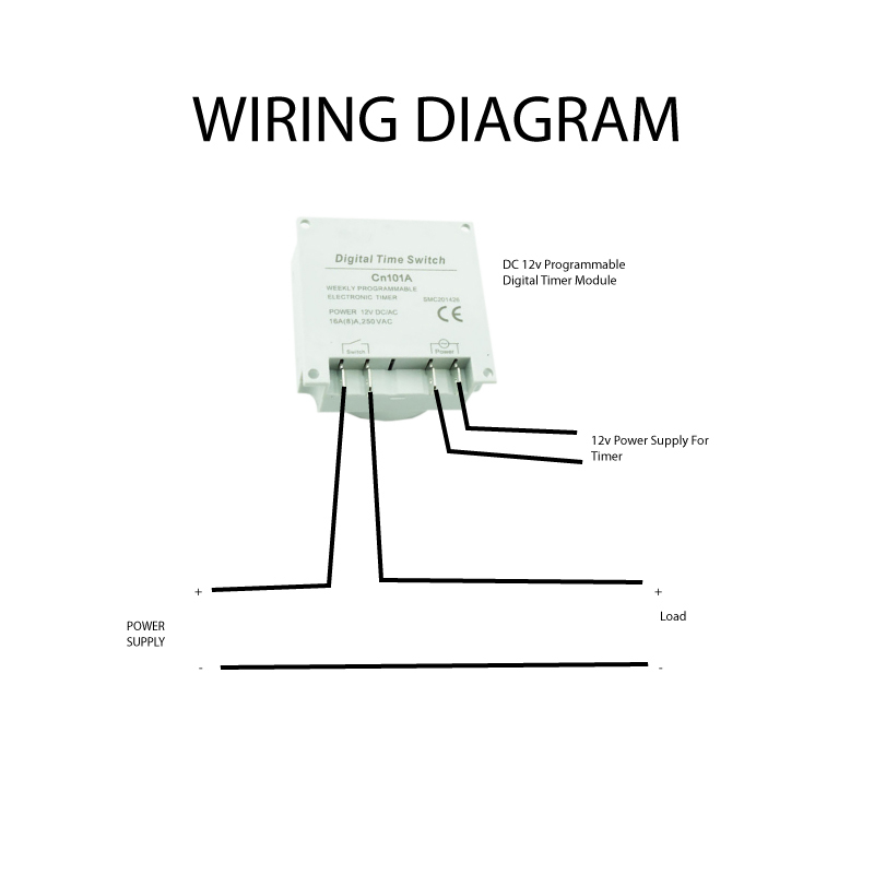 12v Timer Wiring Diagram Wiring Diagram

 Adjustable Timer Circuit Diagram With Relay Output


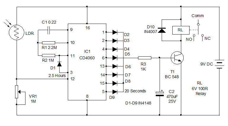 Types Of Timer Circuits With Schematics And Its Working
 Hager Timer Switch Wiring Diagram Diagrams Typical Walk In


0 Response to "Timer Switch Circuit Diagram"
Post a Comment