Ph Diagram For Refrigeration Cycle
This case is also to evaluate various cycles such as with penalties economizing for a single stage compression refrigeration systems which are based on the same ct et and tr as the following. Gases give off heat when changed from gas to liquid.
 Jsrae Japanese Society For Refrigerating And
Yoshihiro udagawa toshiba carrier corporation.

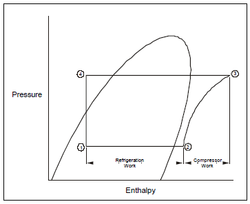
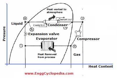
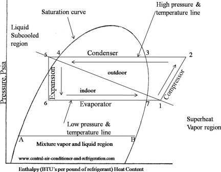
Ph diagram for refrigeration cycle. Remember refrigeration cycle diagram will always have the same basic components compressor condenser expansion device evaporator and refrigerant tube. Figure 13 shows the components in the cycle and figure 14 shows the basic cycle on the ph diagram. Please provide feedback on this module by selecting like or dislike.
Learn how to draw a cycle for ideal conditions on a ph chart. 23 the basic cycle in a log ph diagram experts in brazed plate heat exchangers swep is a world leading supplier of brazed plate heat exchangers for hvac and industrial applications. Your feedback and comments is important to me in developing.
4 2 1 compressor evaporator. These components may be in difference shape capacity and size but it does the same thing. If we understand how the refrigeration cycle works well understand how any air conditioner works.
Thermodynamic analysis of the refrigeration cycle using the p h diagram. Saturation curve this curve represents what state vapor or liquid and region sub cooled latent heat and superheat the refrigerant is in. The refrigerant flow diagram corresponding to the p h diagram.
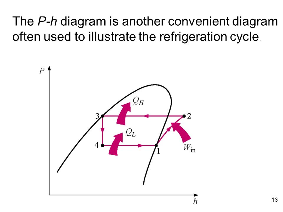
For an air conditioning system to operate with economy the refrigerant must be used repeatedly. The following post gives background information on the refrigeration cycle as shown on the pressure enthalpy diagram. This is the definition of 1 ton of refrigeration.
Bahrami ensc 461 s 11 refrigeration cycle 3 fig. An important skill that is necessary to pass the pe exam is the ability to navigate a refrigerants pressure enthalpy diagram and to be able to follow the vapor compression cycle on the p h diagram. As we can see in the ph diagram below.
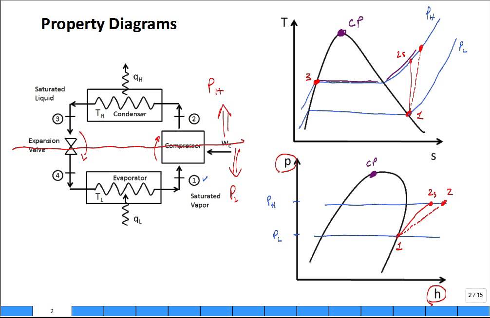
Ideal basic refrigeration cycle the ideal basic refrigeration cycle consists of four components connected by piping with refrigerant flowing through the system. The saturated vapor at state 1 is superheated to state 2. Understanding the basic refrigeration cycle diagram also helps us to find subcooled superheat and to troubleshoot refrigeration processes much easier.
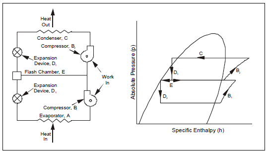
A reversible adiabatic isentropic compression of the refrigerant. Lets study about how to draw a refrigerant cycle in series using the documents with courtesy of mr. When you can draw a refrigeration cycle on a p h diagram you can easily obtain the refrigerant characteristics through the diagram.
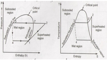
Liquids absorb heat when changed from liquid to gas. T s and p h diagrams for an ideal vapor compression refrigeration cycle. A p h diagram for r22 in si unit is used.
Wc h2 h1. The mechanical pe exam covers the topic of refrigeration.

 Vapour Compression Systems Refrigerants Mcq Test 2 30
 P H Diagram Of The Vapour Compression Refrigeration Cycle
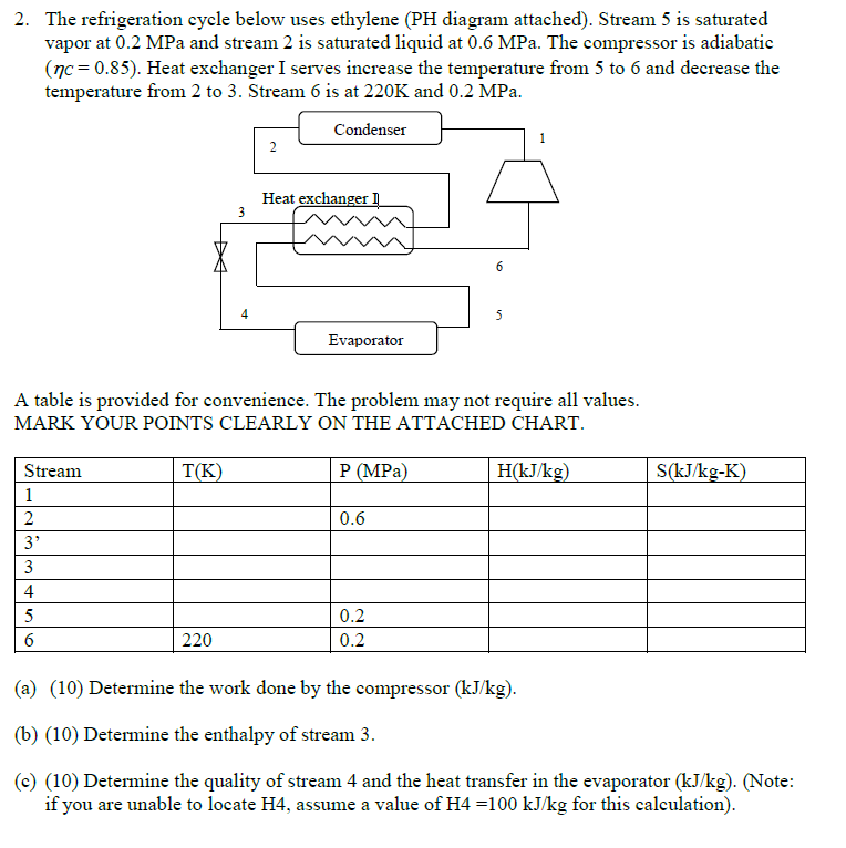 Solved 2 The Refrigeration Cycle Below Uses Ethylene Ph
 Thermodynamics How To Find The Entropy For A Given
 Figure 1 From Analysis Of Refrigeration Cycle Performance

Chapter 10 Refrigeration Cycles
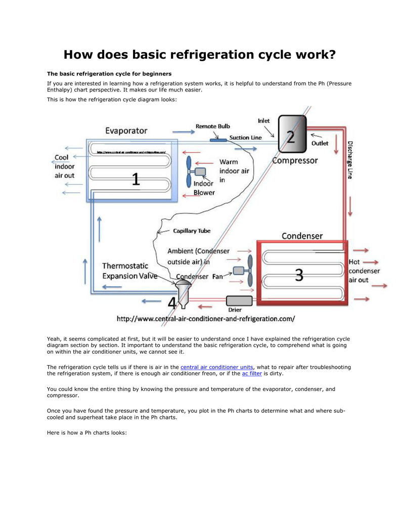 How Does Basic Refrigeration Cycle Work
 A Refrigerator Or Heat Pump That Operates On The Reversed
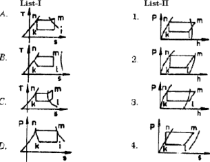
 Draw T S And P H Diagram Of Sub Cooled And Super Heat Vapour
 Draw P H And T S Diagram When The Vapours Are Superheated At
 2 1 The Pressure Enthalpy Diagram Swep
 Gas Processing Mechanical Refrigeration
 An Ordinary Household Heat Pump 9 The P H Diagram Of An
 Ex Four
 Ideal Vapour Compression Refrigeration Cycle In P H Diagram

 P H Diagram Of Vapor Compression Refrigeration Cycle
 Property Diagrams Ts And Ph For Refrigeration 2
 Refrigeration Cycles د محمود عبدالوهاب Ppt Download
 2 4 The Complex Cycle In A Log Ph Diagram Swep
0 Response to "Ph Diagram For Refrigeration Cycle"
Post a Comment