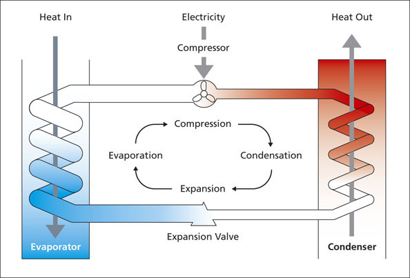
Heat Pump Cycle Diagram
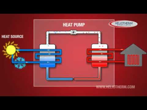
The thermodynamic cycle the log p h diagram shows a cycle for a mechanical heat pump. The difference in the two diagrams is the reversing valve 2 directs the compressed refrigerant to the inside coil first.
 The Vapour Compression Cycle Heat Pump Association
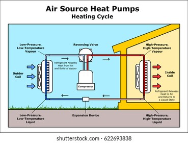
The diagram above shows the heat pump in heat mode.
Heat pump cycle diagram. Thermodynamic heat pump cycles or refrigeration cycles are the conceptual and mathematical models for heat pumps and refrigerators. This makes the inside coil the condenser and releases the heat energy 3 4. Sign into the forum contractor.
Simplified piping diagram of a heat pump swimming pool heater. The heat pump is very simple once you understand the basic concept and i promise you will after reading this. This allows a heat pump to provide year round indoor comfort no matter what the season is.
As they say a picture worth a thousand words. An air source heat pump uses advanced technology and the refrigeration cycle to heat and cool your home. Heat pump in air conditioning mode.
If the system is not using a pressure tank the answer is yes. This heated air is ducted to the home. The ts diagram shows an ideal double cascade system using the same refrigerant in.
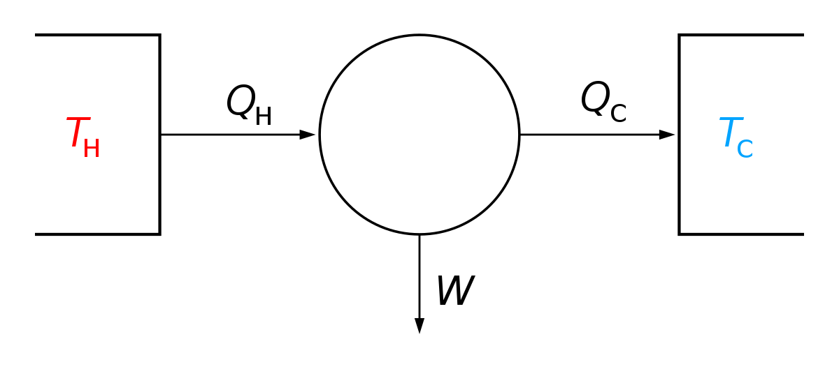
The points represent the different components of the heat pump. A heat pump is a mechanical system that allows for the transference of heat from one location the source at a lower temperature to another location the sink or heat sink at a higher temperature. Toggle navigation answers in minutes.
This means that the pump will cycle on and off with the heat pump and can in the event of system short cycling lead to. When properly installed and functioning a heat pump can help maintain cool comfortable temperatures while reducing humidity levels inside your home. In this diagram a heat pump with a condensation temperature of 80 c and an evaporation temperature of 40 c is taken as an example.
The condenser of a low temperature cycle provides the heat input to the evaporator of a high temperature cycle eg 2 units in series normally a different refrigerant would be used in each separate cycle in order to match the desired ranges of t p. As the name suggests a heat pump transfers or pumps heat from one place to another notice the use of the word pump heat is not generated but rather is moved. A heat pump is a device that transfers heat energy from a source of heat to a destination called a heat sink.
A collection of heat pump diagrams are available in the following printable diagramsthe images that we have collected below show the illustrations on how to make a heat pump installation wiring and work.

 Image Result For Refrigerator And Heat Pump Thermodynamics


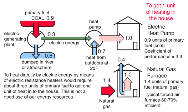
 Heat Pumps The New High Tech Energy Source On Air Lg
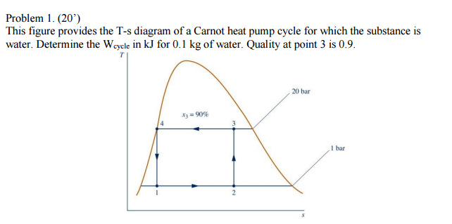
Solved This Figure Provides The T S Diagram Of A Carnot H
 Integrated Carbon Dioxide Heat Pumps And Water Heaters
 T S Diagram Of The Improved Model Heat Pump Cycle For R134a
 Thermodynamics Ebook Carnot Refrigerator And Heat Pump
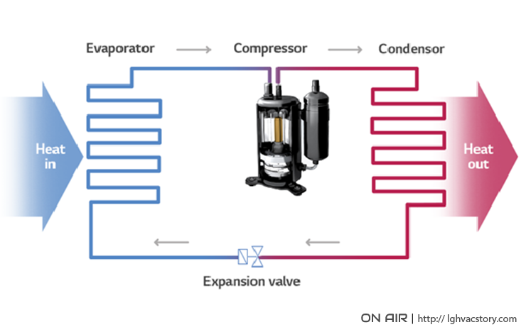 Heat Pumps The New High Tech Energy Source On Air Lg
 Thermodynamics The Second Law Of Thermodynamics Wikiversity

 The T S Diagram Of A Theoretical Heat Pump Cycle For A
 Carnot Cycle Of Heat Pump A Schematic Diagram B Vapor
 Heat Pump Cycle
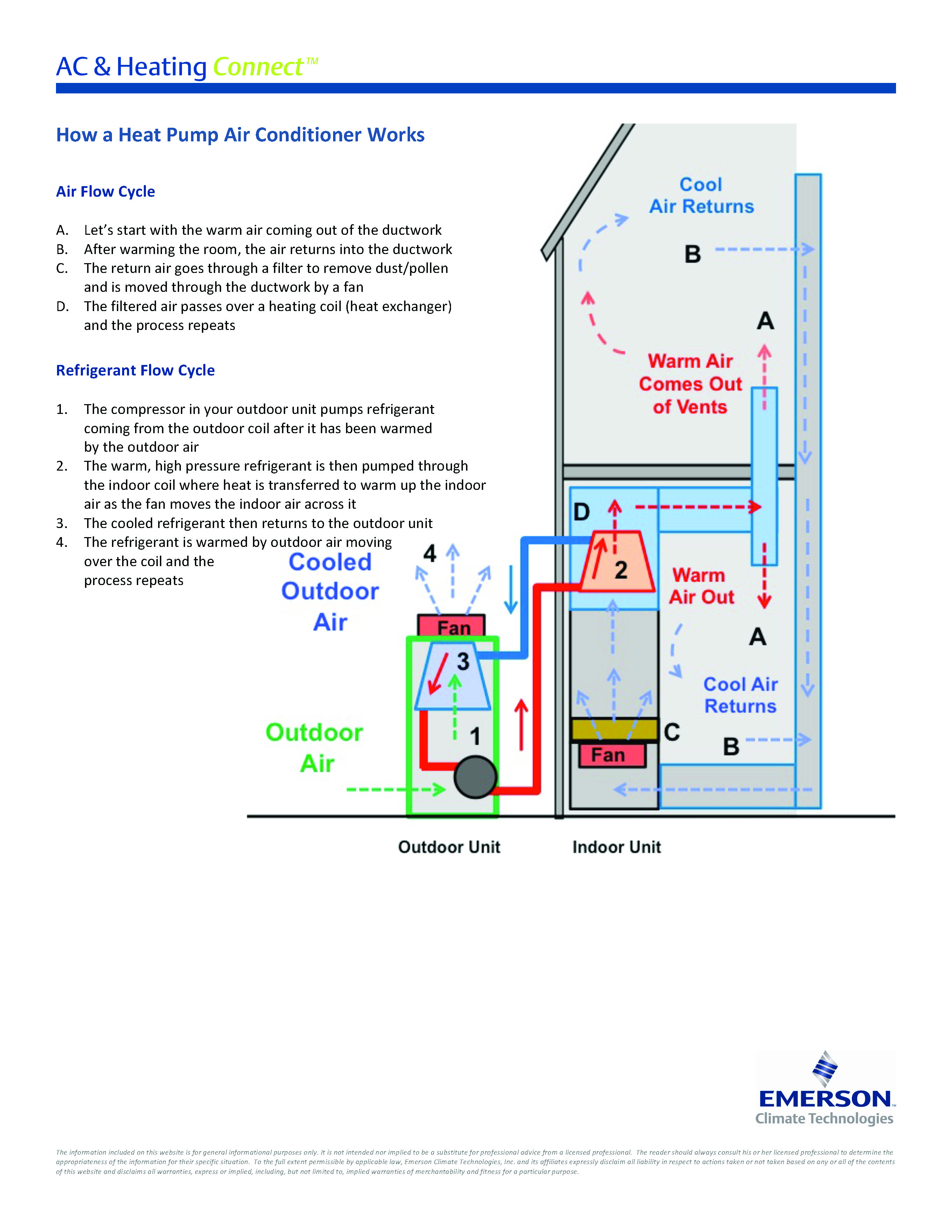 How A Heat Pump Air Conditioner Works Ac Heating Connect
 Refrigeration Cycle Images Stock Photos Vectors
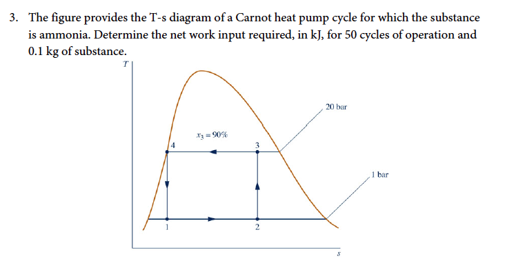 Solved The Figure Provides The T S Diagram Of A Carnot He
 Thermodynamic Cycle Wikipedia
 Figure 3 From Design And Thermodynamic Analysis Of A Steam

 How Heat Pumps Work Heat Pumps Air Conditioning

 Heat Pump Principles
0 Response to "Heat Pump Cycle Diagram"
Post a Comment