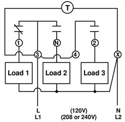
Paragon Defrost Timer Wiring Diagram
The dtav40 may also be used to replace paragon 8040 and precision 6040 series time terminated defrost timers. It reveals the elements of the circuit as simplified forms and also the power and also signal connections between the tools.

Wiring diagram for paragon 8145 20 defrost timer paragon 8145 20 defrost timer question.

Paragon defrost timer wiring diagram. To understand why paragon. Posted by anonymous on apr 28 2012. Appliances cheaper 22629 views.
Collection of paragon 8141 00 wiring diagram. It shows the components of the circuit as simplified forms as well as the power and signal connections between the devices. A wiring diagram is a streamlined standard pictorial representation of an electrical circuit.
Browse categories answer questions. How to replace an expensive adaptive defrost timer with a low cost manual defrost timer duration. Collection of paragon defrost timer 8145 20 wiring diagram.
Many of the refrigeration appliances used in the home are frost free the frost free appliance could more accurately be termed automatic. A wiring diagram is a streamlined traditional pictorial depiction of an electric circuit. A wiring diagram is a simplified traditional photographic depiction of an electric circuit.
Variety of walk in freezer defrost timer wiring diagram. A wiring diagram is a simplified traditional photographic depiction of an electrical circuit. Defrost timer circuits schematic diagram sample and definition.
Applications and wiring diagrams mechanical defrost timer 8000 series. The brain of the frost free appliance is the defrost timer. Httpadfly1r9lly precisely why should imagine more.
Defrost timer circuits schematic diagram sample and definition. Reading the book wont spend or waste your time and energy will a person. Wiring diagram for paragon 8145 20 defrost timer.
Collection of paragon defrost timer 8145 20 wiring diagram. It shows the components of the circuit as simplified forms and also the power as well as signal connections in between the gadgets. Freezer defrost timer live operation on testing board.
The dtav40 defrost timer is equivalent in function terminal identification with appropriate terminal block label attached and wiring to the paragon 8140 and precision 6140 series defrost timers. Defrost timer 8000 series defrost duration solid copper contacts line voltage 120208 240v ac 40 amp 2 hp pins indicate defrost start time time of day model number time initiated. Paragon 8145 20 defrost timer.
It reveals the elements of the circuit as streamlined shapes and also the power as well as signal links in between the tools.


 Paragon Defrost Timer Wiring Schematic Wiring Diagram

 Freezer Defrost Timer Wiring Diagram Mars 3 In 1 Awesome


 Paragon 8141 00 Wiring Diagram Amazing Paragon Defrost Timer


 Paragon Defrost Timer 9145 Wiring Diagram For Am At Switch
 I Have An 8141 Paragon Defrost Timer And Have To Replace It
 Paragon Defrost Timer 9145 Wiring Diagram For Am At Switch


 Refrigerator Defrost Timer Wiring Diagram Free Wiring Diagram
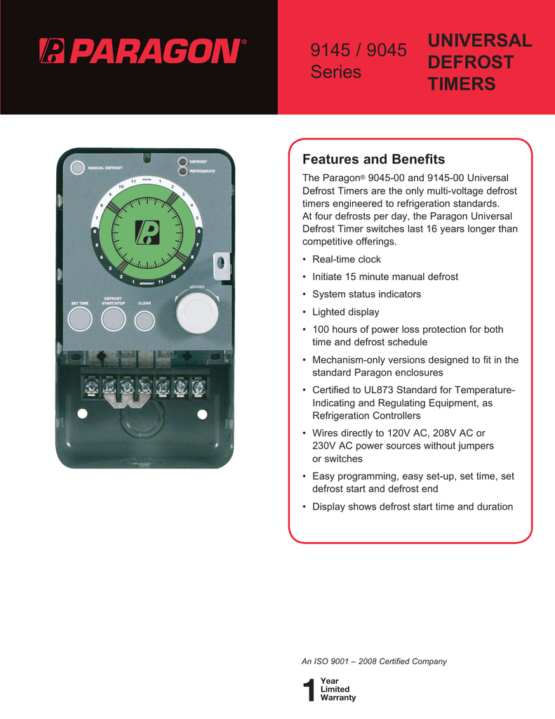 Universal Defrost Timers 9145 9045
 Paragon 8145 20 Wiring Diagram Wiring Diagram

 Paragon 8141 00 Wiring Diagram Easy Defrost Timer 8141 20

0 Response to "Paragon Defrost Timer Wiring Diagram"
Post a Comment