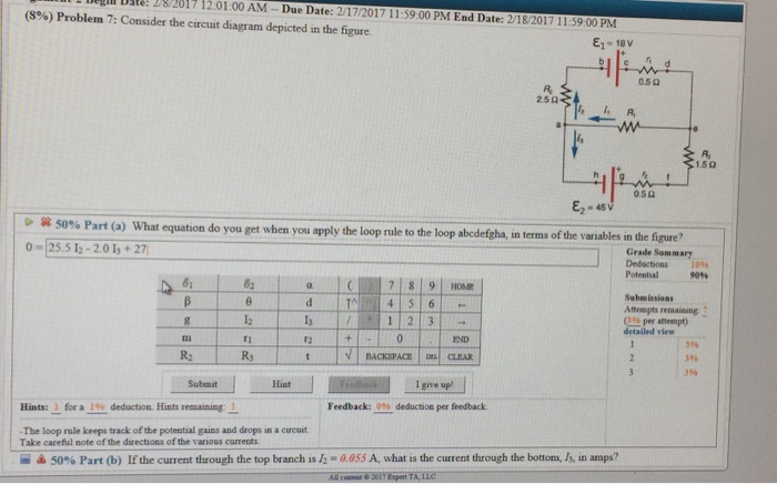
Consider The Circuit Diagram In The Figure
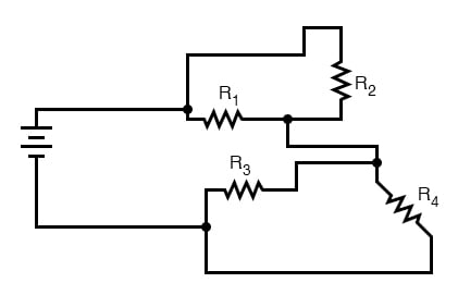
Lastly 17 ohms is by itself if that helps. The rectangular boxes in the diagram are the resistors.
 Parallel Rlc Circuit And Rlc Parallel Circuit Analysis
A what equation do you get when you apply.
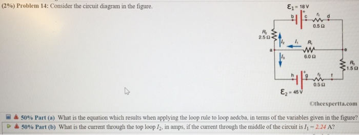
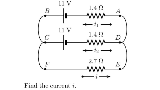
Consider the circuit diagram in the figure. Sum the voltage changes across each circuit element around this loop going in the direction of the arrow. B if the current through the top branch is i 2 0605 a. Consider the circuit in the figure with the current directions defined as shown.
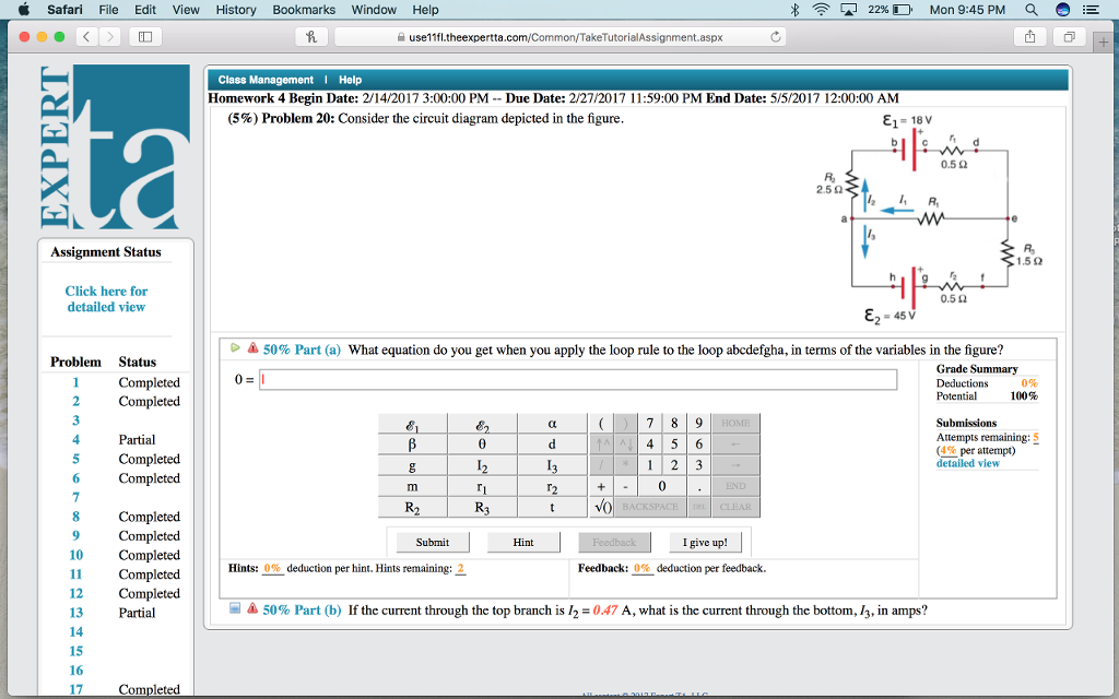
Consider the circuit diagram depicted in the figure. Consider the circuit diagram depicted in the figure. Figure 12111 a a purely capacitive circuit and b a purely inductive circuit.
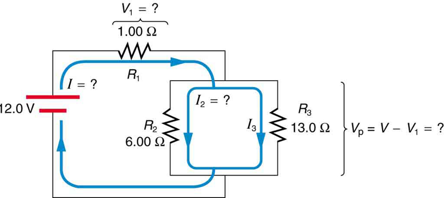
The inductor has a reactance 0 300 v v 1300 l x ω. Then it splits off to 10 ohms and 10 ohms being in a parallel circuit. There are four resistors in this circuit r 1 r 2 r 3 and r 4 and four batteries with emfs ac 1 185 v.
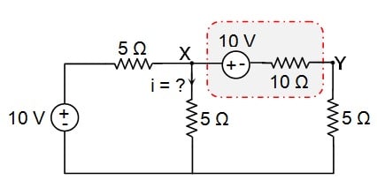
Consider the electric circuit shown in the figure. Draw a circuit diagram. While kirchhoffs junction law is needed only when there are one or more junctions in a circuit kirchhoffs loop law is used for analyzing any type of circuit as explained in the following tactics box.
Remember that the current meter is ideal. 20 and 90 ohms are in a series while both are in a parallel with 5 ohms. A what equation do you get when you apply the loop rule to the loop abcdefgha in terms of the variables in the figure.
B if the current through the top branch is i 2 038 a what is the current through the bottom i 3 in amps. A what equation do you get when you apply the loop rule abcdefgha in terms of the variables in the figure. The light bulb in the circuit diagram of figure 1 has a resistance of 070 ohm.
Tactics box 231 using kirchhoffs loop law 1. By a circuit the sum of these potential differences must be zero. Now apply the loop rule to loop 1 the larger loop spanning the entire circuit.
Find a the time constant of the circuit and b the maximum charge on the capacitor. Consider the potential difference between pairs of. Sum the voltage changes across each circuit element around this loop going in the direction of the arrow.
Consider the circuit diagram depicted in the figure. Consider a series rc circuit as in the figure below for which r 100 mω c 500 µf and ε 300 v. B a 45 mh inductor is connected as shown in figure 12101b to an ac generator with.
Assume that v 128 v r1 r2 r3 r4 r5 200 ω.
 Open Circuit Test Wikipedia
 Analyzing Circuits Via Source Transformation
 Re Drawing Complex Schematics Series Parallel Combination
Solved 1 Is Mass And A I Is The Change In Temperature 3
 Consider The Following Figure Assume V 9 V R 1 2 2
 Series Rlc Circuit And Rlc Series Circuit Analysis
 Solved Consider The Circuit Diagram Depicted In The Figur
 The Schematic Diagram A Basic Element Of Circuit Design
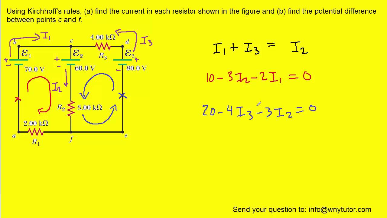 Using Kirchhoff S Rules Find The Current In Each Resistor Shown In Figure
 The Schematic Diagram A Basic Element Of Circuit Design
 Wiring Diagram Everything You Need To Know About Wiring
 Schematic Diagram Of A Two Neuron Winner Take All Circuit
 Current Through Resistor In Parallel Worked Example
 Ohm S Law Electric Circuits Siyavula
 Consider The Circuit Shown In The Diagram Find The Current
 Consider The Circuit Shown In The Diagram Find The Current In 3
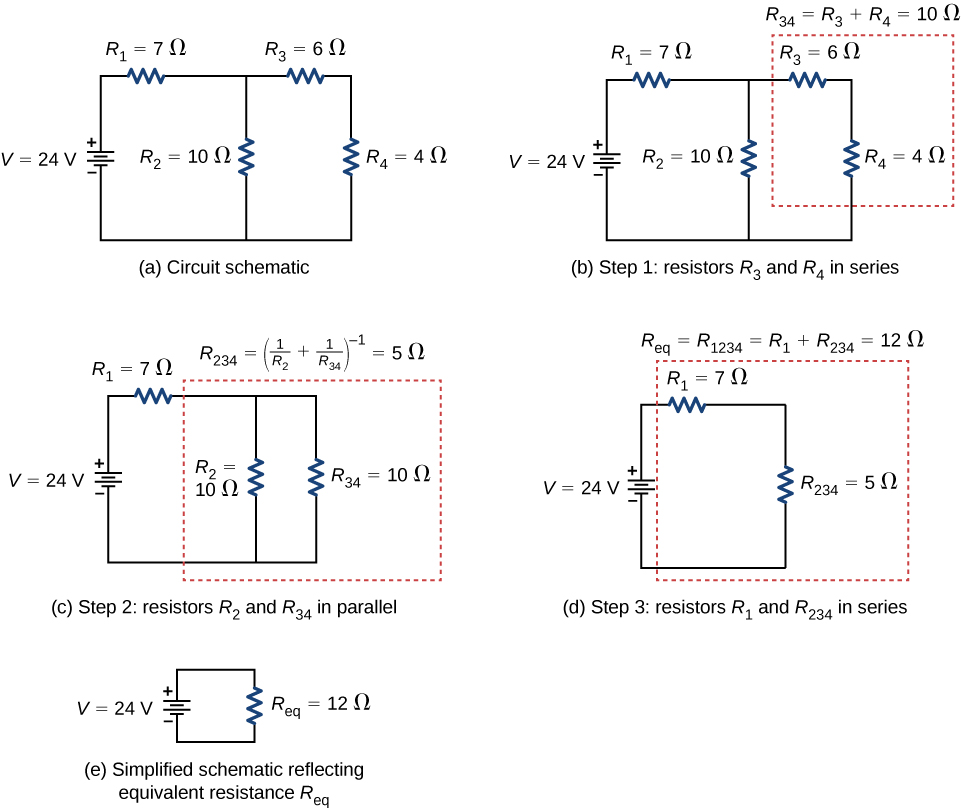 10 2 Resistors In Series And Parallel Physics Libretexts
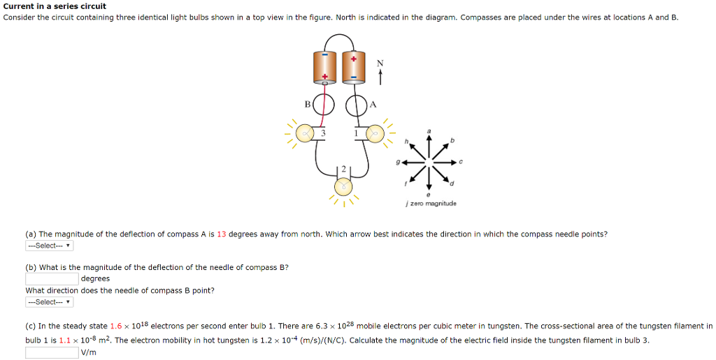 Figure 4 A Series Circuit Diagram Showing Wire Three Light
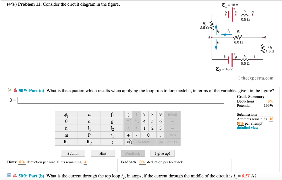 Solved 4 Problem 11 Consider The Circuit Diagram In T
 Consider The Circuit Diagram Depicted In The Figure Free
 Draw Circuit Diagram Showing A Dry Cell Connected To A Bulb
 Resistors In Series And Parallel College Physics
0 Response to "Consider The Circuit Diagram In The Figure"
Post a Comment