4 Wire Pressure Transducer Wiring Diagram
Arduino forum using arduino sensors pressure sensor. Variety of 4 wire oxygen sensor wiring diagram.
![]() 3 Wire Transducer Wiring Diagram Schematics Online
3 Wire Transducer Wiring Diagram Schematics Online
These wiring options include.
4 wire pressure transducer wiring diagram. Hi everyone im sure lots of people can give a straightfoward answer to this. 4 20 ma transmitter wiring. 4 ma to 20 ma two 8wire output 1015 2n.
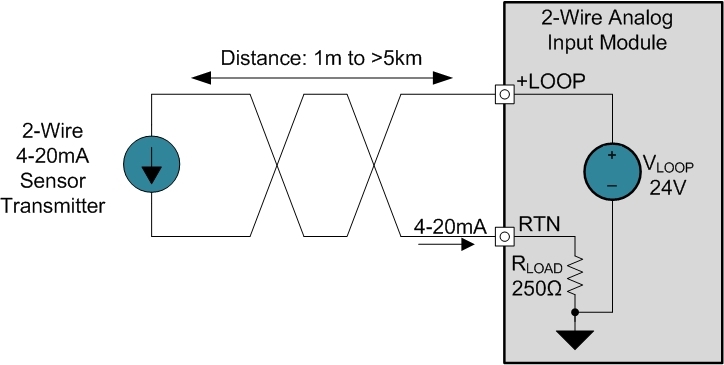
It so happens that on some vehicles cadillacs the high pressure sensor is connected to the other sensor voltage reference line. 4 ma to 20 ma three wire output10 2k. The sensor consumes 4ma at atmospheric pressure and 20 ma at 1 bar by using the 250 ohm resistor i have a voltage.
While reviewing the wiring diagram on some pressure transmitters 2 wire 4 20ma output direct wire im about to buy i noticed a slight inconsistency with the wiring in the ni9203 user manual. Help wiring a pressure transducer. General purpose gageabsolute pressure transducer model z features 025 accuracy.
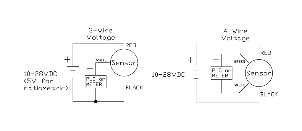
2 wire for current transducers and 3 wire for voltage transducers. Next disconnect the wire form the transducer that is connected to the control circuit and place the lead form the digital milliamp meter to the black wire. So a shorted sensor will render the crank sensor inoperable.
The design of the associated control panel dictates which option should be used. In this video we show you how to wire a pressure transducer two ways. Register login.
Several transmitter wiring options exist. Troubleshooting a 4 20ma transducer. Swagelok pressure transducers following the ni9203 manual the ve.
Current source transmitter non isolated 3 wire current sink transmitter non isolated 3 wire fully isolated 4 wire two wire loop powered transmitters. Help wiring a pressure transducer justinvandenbos ch. A wiring diagram is a streamlined standard pictorial depiction of an electrical circuit.
In your case i would wire the excitation wire from your pressure transducer to your 5v source and then i would wire the common or black wire from your pressure transducer to the commonground of that power. Here are links to the user manuals for the sensors. General purpose gageabsolute pressure transducer range codes pressure range psi.
2n 4 ma to 20 ma two 8wire intrinsically safe 1015. Pressure sensor no wiring diagram. When the transducer is still connected to the pipeline and control circuit connect the 24 vdc to the red wire of the transducer.
It reveals the components of the circuit as streamlined forms and also the power as well as signal links between the tools. Do anyone know how to connect wire this sensor and read the value using an arduino uno.
![]() Pressure Transmitters Wire Configuration Learning
Pressure Transmitters Wire Configuration Learning
![]() Pressure Transducers And Transmitters
Pressure Transducers And Transmitters
![]() 3 Wire Pressure Transducer Wiring Diagram Luxury Pirani
3 Wire Pressure Transducer Wiring Diagram Luxury Pirani
![]() Pressure Transducer Wiring Diagram Wiring Forums
Pressure Transducer Wiring Diagram Wiring Forums
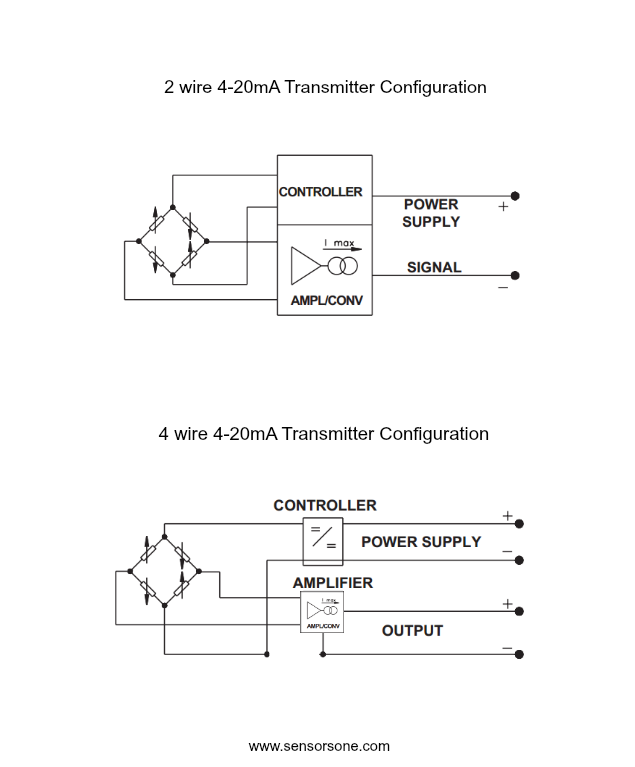
![]() 4 20 Ma Transmitter Wiring Types 2 Wire 3 Wire 4 Wire
4 20 Ma Transmitter Wiring Types 2 Wire 3 Wire 4 Wire
 4 20ma Wiring Diagram User Guide Of Wiring Diagram
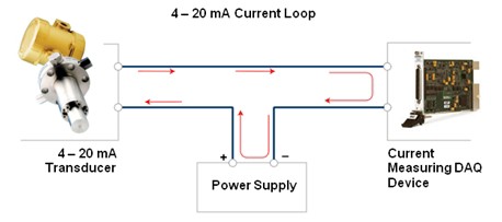
 4 To 20 Ma Current Loop Output Signal
 4 Wire Pressure Transducer Wiring Diagram Wiring Diagram T1
 Pt100 Wiring Diagram Wiring Diagram Schematics
 Pressure Wiring Diagram Wiring Diagram
![]() 3 Wire
3 Wire
![]() 4 Wire Pressure Transducer Wiring Diagram Wiring Diagram T1
4 Wire Pressure Transducer Wiring Diagram Wiring Diagram T1
 3 Wire 4 20ma Wiring Diagram Schematic Wiring Diagram
 Pressure Transducer Wiring Diagram Wiring Diagrams Sign
 2 Wire Transmitter Wiring Diagram Amazing Wiring Diagram
![]() 4 Wire Pressure Transducer Wiring Diagram Wiring Library
4 Wire Pressure Transducer Wiring Diagram Wiring Library
 Voltage Output Pressure Transducer Comparison Te Connectivity
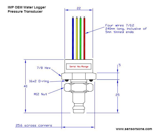
![]() Imp Low Cost Pressure Sensor
Imp Low Cost Pressure Sensor
How To Connect To An Ethernet Device For Communication

 Pressure Transducers Pressure Transmitters Pressure Sensors

 4 3 Sensor Wiring Wiring Diagrams Folder
 Tphada Ultra High Range Pressure Sensor
 Pressure Sensors The Design Engineer S Guide Avnet Abacus
![]() How Do Pressure Transducers Work Omega Engineering
How Do Pressure Transducers Work Omega Engineering
![]() Get 4 20ma Pressure Transducer Wiring Diagram Sample
Get 4 20ma Pressure Transducer Wiring Diagram Sample
0 Response to "4 Wire Pressure Transducer Wiring Diagram"
Post a Comment