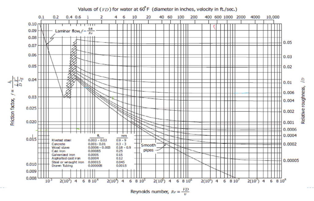
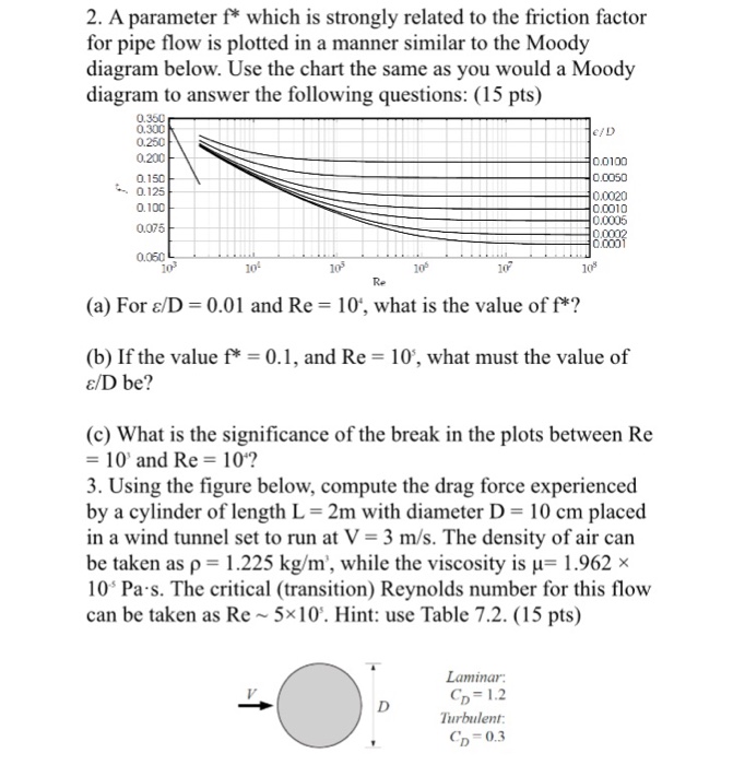
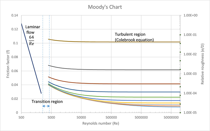
How To Use Moody Diagram
If you try to solve this factor directly much complexity is experienced. Si based moody diagram.
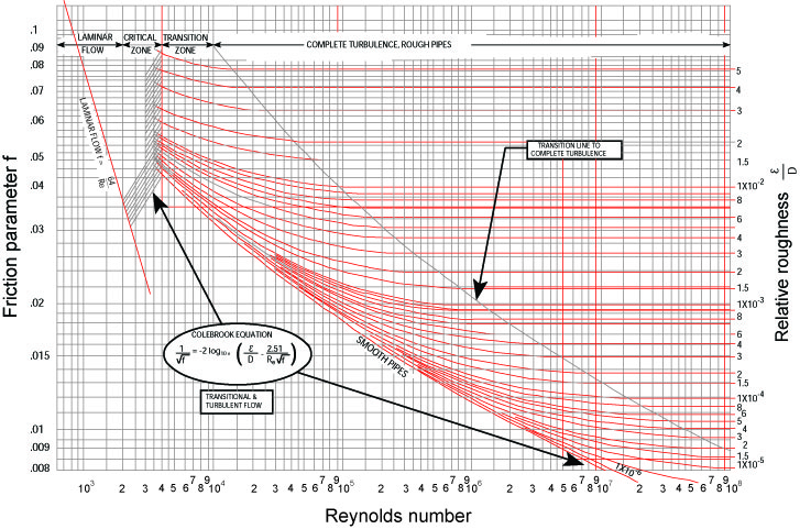
Determination Of Friction Coefficient In Transition Flow
In these cases moody diagram or moody charts are really handy.
How to use moody diagram. A moody chart is commonly used by engineers to calculate the darcy weisbach friction factor which is then in turn used to calculate headpressure loss due to friction in pipes. For circular pipes the problems can be solved using swamee jain equation but for the other types it is really difficult. Whether the flow is steady or transient we have to use it.
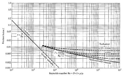
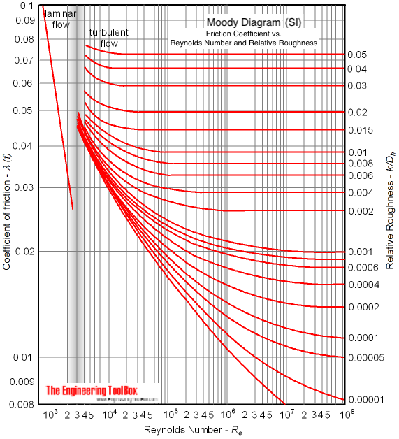
That is a fluid mechanics question which is outside my field of expertise. On the moody chart the friction factor is shown on the left hand y axis the reynolds number is shown on the x axis and the relative roughness is shown on the right hand y axis. The moody friction factor λ or f is used in the darcy weisbach major loss equation.
Make architecture diagrams online. The coefficient can be estimated with the diagram below. Another common mistake when reading the moody diagram is improper interpolation between lines and points.
Use lucidchart to map out your software design and architecture. Sign up for a free trial today. If the flow is transient 2300 re 4000 the flow varies between laminar and turbulent flow and the friction coefiicient is not possible to determine.
Both the reynolds number and relative roughness are unitless values when computed correctly therefore the moody chart is unitless so the same chart applies to us customary and si unit systems. However there are some good resources on the web which covers this.

 Losses In Pipes
 Chemical Files Friction Factor Confusion
 Solved Please Use Graphs And Charts Provided To Solve Pro
 25 Always Up To Date Moody Chart Friction Factor
 Moody Diagram Excel Wiring Diagram Document Guide
Chapter 7 Flow Through Pipes
 Moody Diagram Moody 1944 Reproduced By Permission Of
 Fanning Friction Factor Wikipedia
Basic Fluid Mechanics Major Losses Colebrook White Equation

 Moody Diagram For The Determination Of Flow Regimes With
 Moody Diagram Moody 1944 Reproduced By Permission Of
 Moody Diagram Excel Wiring Diagram T1
 Friction Factor An Overview Sciencedirect Topics
 Moody Diagram
Use Of Excel For Pipe Flow Friction Factor Head Loss
 Moody Chart Wikipedia
 Moody Diagram Friction Loss
 Chemical Files Friction Factor Confusion
 Moody S Friction Factor Calculator Towards Open Science
Basic Fluid Mechanics Major Losses Colebrook White Equation
0 Response to "How To Use Moody Diagram"
Post a Comment