Fuel Sending Unit Wiring Diagram
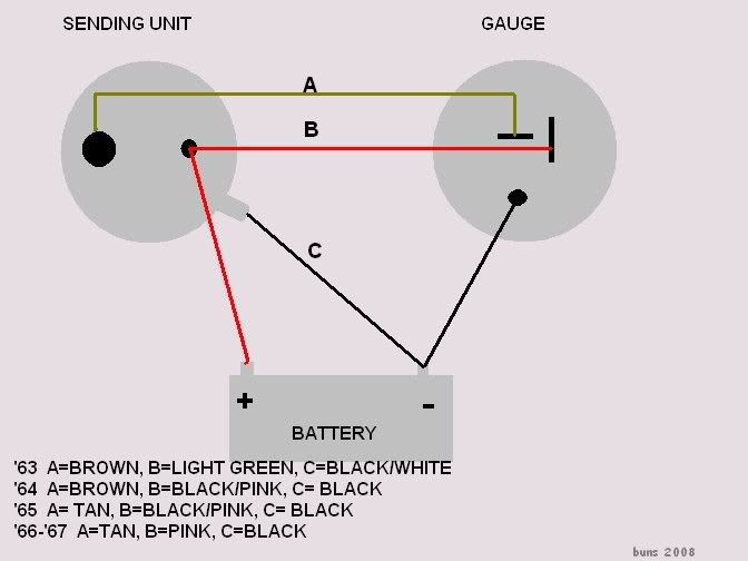
Electric sending unit to fuel gauge wiring diagram. Next connect a wire from the float on the fuel tank to the negative terminal of the fuel gauge.
 Marine Fuel Sending Unit Wiring Diagram Moreover Temperature
Position new unit above tank aligning screw hole pattern in the mounting flange with hole pattern in top of tank.

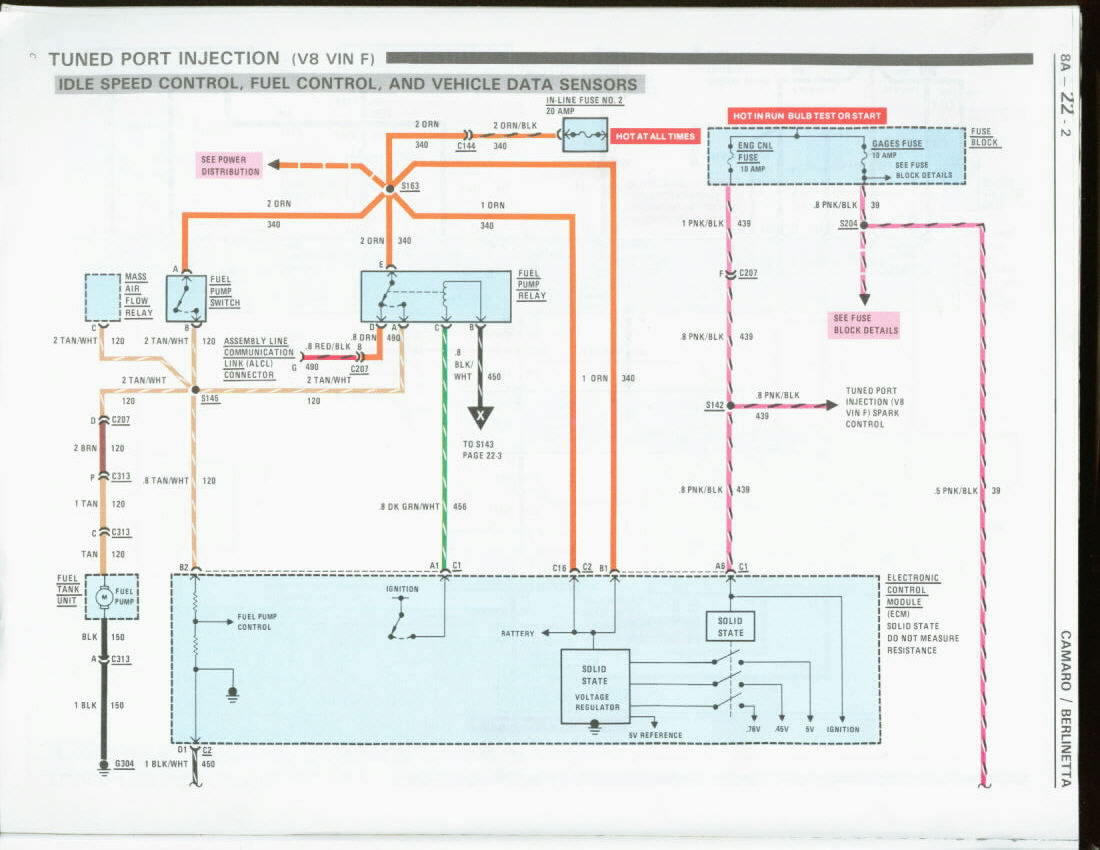
Fuel sending unit wiring diagram. Refer to the vdo catalog for matching fuel gauges. Measure the depth of your fuel tank. The fuel gauge reads the resistance to ground check the wires on the back of the gauge pink to s terminal and black to g terminal.
The older float style which uses a magnet embedded in a float that resides in a tube sending readings of how high in the tank it is floating and there is the newer style that measures electrical. Parts of the fuel level sender unit to be ad fuel level sender installation. S for the sender g or for the ground and i for the ignition.
Note the direction of movement of the old float arm to assist installation. The unit can be adjusted to read accurately in tanks from 6 to 23 deep. Check the wiring diagram that comes with the kit and mark the back of the new fuel gauge with symbols for each post.
The sending unit will ground through the mount screws. Always disconnect battery ground before making any electrical connections. Install the new gauge reconnect the wiring and turn on the power.
A wiring diagram is a simplified traditional photographic representation of an electrical circuit. Wire a fuel gauge by first disconnecting the old dysfunctional unit to replace it with a new one. The fuel tank should be grounded and the sender wire pink should be connected to the sender terminal on the sending unit this is the correct wiring.
There are two types of sending units. It shows the elements of the circuit as streamlined forms as well as the power as well as signal links between the devices. The fuel gauge should now show the correct fuel level in the tank.
Assortment of fuel gauge sending unit wiring diagram. Obtain 12 volt power from the fuse box using a standard wire and connect it to the positive terminal of the fuel gauge. The fuel sending unit is responsible for what the fuel gauge on your vehicle reads.
Replace an existing fuel sender by removing the old unit.
 1965 1966 Chevy Impala Gas Fuel Tank Sending Unit 3 8 Line
 04 Dodge Ram Fuel Sending Unit Wiring Swift Electrical Schemes

 Fuel Gauge And Sending Unit Wiring Diagram Wiring Schematics


 55 Ford Fuel Sending Unit Wiring Diagram Wiring Diagrams
 Wiring Diagram 99 Fuel Sending Unit Toyota 4runner Forum

 Wiring Diagram For Gas Gauge Diagrams Tar Truck 19 Headlight

 78 Ford Fuel Sending Unit Wiring Wiring Diagrams Folder

 Ebay Fuel Cell Sending Unit Wiring Diagram 2 Wire Trim For
 Gm Fuel Sending Unit Wiring Diagram Lovely Gm Fuel Sending
 64 Fuel Sending Unit Wiring Question Corvetteforum
 Marine Fuel Sending Unit Wiring Diagram Moreover Temperature

 Ford Fuel Sending Unit Wiring Wiring Diagram Document Guide
 Fuel Sending Unit Wire Diagram Corvetteforum Chevrolet
 1973 Ford F 250 Fuel Sending Unit Wiring Wiring Diagram
 Fuel Sending Unit Wire Diagram
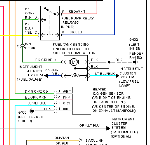
 Fuel Sending Unit Wiring Diagram To Pcm And Instrument


 Sending Unit Plug Wiring Diagram Amazing Wiring Diagram
0 Response to "Fuel Sending Unit Wiring Diagram"
Post a Comment