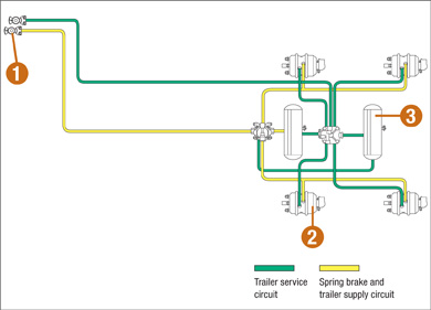
Trailer Air Brake System Diagram
Instead the system park valve commonly referred to as the parking brake would be used because its operation results in both tractor and trailer spring brakes being applied. This diagram provides both a closeup view and an example of where the brakes are located in your vehicle.
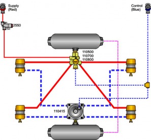
Mixed brake chambers with control.

Trailer air brake system diagram. The brake pedal. These diagrams are provided for basic identification only. Relays are fitted to an air braking system for larger vehicles to speed up the application and.
Typical 6 wheel air brake system. Always consult a professional technician to. Non towing semi non spring brake pre fmvss 121 with hostler valve.
Tandem axle semi trailer pre fmvss 121 single tank non spring brake. Non anti lock brake abs air piping diagrams. A more detailed look at the air braking system in particular with this video at the air brake relay.
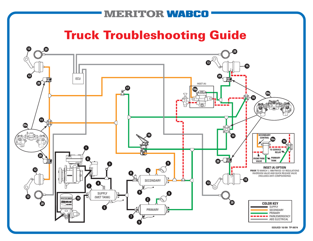
Typical 10 wheel brake system. Trailer systems troubleshooting guide how to use this chart the purpose of the chart is to help you solve a specific problem in the pneumatic portion of a trailer air brake system with the assumption the foundation brake components and tractor pneumatics are in good repair. These diagrams are provided for basic identification only.
Single tank a1000s with service chambers only. Trailer air brake system diagram see more about trailer air brake system diagram agricultural trailer air brake system diagram bendix trailer air brake system. Always consult a professional technician to properly troubleshoot your system.
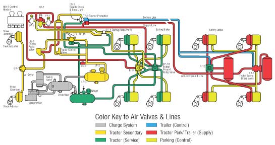
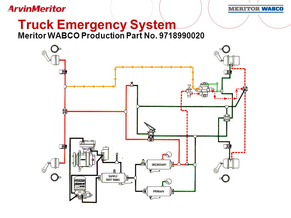
Basic cdl air brake components. The air lines are not coloured coded except the service and supply lines that connect the semi trailer to the tractor or truck. Now lets put the parts together to see how air brakes work as a whole.
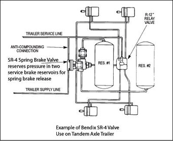
The trailer park valve commonly referred to as the trailer air supply valve is not normally used for parking because it only applies the trailer spring brakes. Single tank a1000s with mixed brake chambers. Basic air brake system schematics.

 Air Brake Valve Diagram Wiring Diagrams Folder
Peterbilt Tractor Wiring Diagram Wiring Diagram
 A General Layout Of The Air Brake System In Trucks
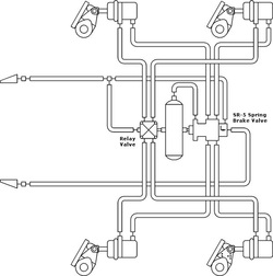
 Simple Tractor Trailer System Sgi
 Basic Air Brake System Schematics
 Air Brake Release Valve

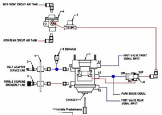
 Air Brake Control Valve
 Checklists Charts And Circuit Diagrams Ontario Ca


 Trailer Parking Brakes
 4 Wheel Disc Brake Plumbing Diagram
 Ezgo Brake System Diagram Wiring Diagram
 A General Layout Of A Truck Air Brake System Download
 Tractor Trailer Air Brake System Diagram Air Brake System
 Air Brakes Schematic Wiring Diagrams
 Trailer Control Systems Truck And Trailer Parts


 Air Brake Systems Ppt Download
 Fire Engine Air Brake Diagram The Best Place To Get Wiring
0 Response to "Trailer Air Brake System Diagram"
Post a Comment