State Machine Diagram Tutorial
State machine diagrams are used to capture the behavior of a software system. As an example the following state machine diagram shows the states that a door goes through during its lifetime.
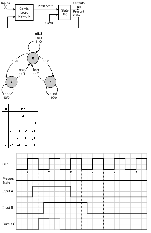 Mealy Finite State Machine Finite State Machines
Using our collaborative uml diagram software build your own state machine diagram with a free lucidchart account today.

State machine diagram tutorial. State machine can be defined as a machine which defines different states of an object and these states are controlled by external or internal events. State machine diagrams commonly known as state diagrams are a useful way of. Activity diagram explained in the next chapter is a special kind of a statechart diagram.
State machine diagrams are also called as state chart diagrams. Tutorial 5 steps to draw a state machine diagram page 2 of 11 3. Now let us discuss about these two state machines one by one.
Uml state machine diagrams can be used to model the behavior of a class a subsystem a package or even an entire system. Use state diagrams the design frameworks for state machines to model the control algorithms you need with discrete logical states. The block diagram of mealy state machine is shown in the following figure.
A statechart diagram describes a state machine. A finite state machine is said to be mealy state machine if outputs depend on both present inputs present states. What is a state machine diagram.
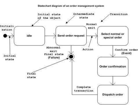
The figure below is an example of a state diagram. This page provides a tutorial for drawing state diagrams in the unified modeling language uml. A state diagram sometimes known as a state machine diagram is a type of behavioral diagram in the unified modeling language uml that shows transitions between various objects.
A state machine diagram models the behaviour of a single object specifying the sequence of events that an object goes through during its lifetime in response to events. State diagrams make it easy to develop and understand the functionality of an application that uses a state machine. Keep reading to learn the basic steps for building these diagrams in lucidcharta free user friendly diagramming platform.
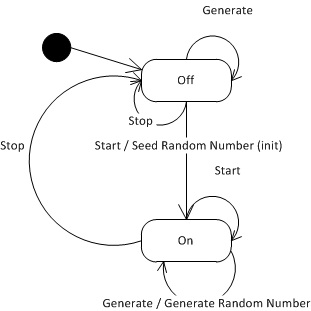
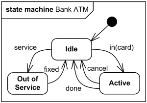
A state machine diagram or start diagram also called state chart of state transition diagram is a behavior which specifies the sequence of states an entity or object visits during its lifetime in response to events together with its responses to those events. The new diagram appears with an initial state a solid black circle by default. Enter bank account as diagram name and click ok to create the diagram.
Uml 2 tutorial state machine diagram state machine diagrams.
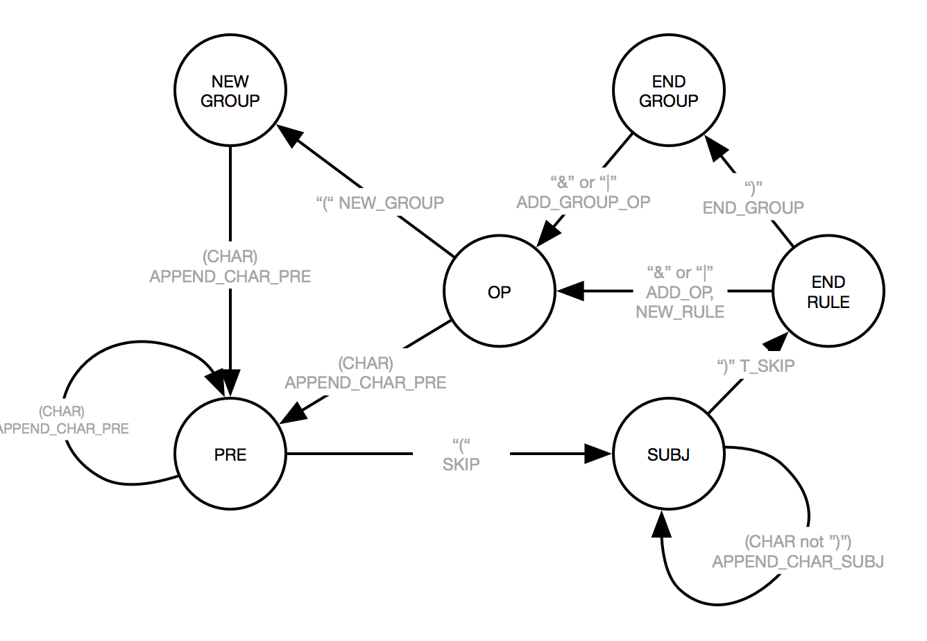
 Generic Finite State Machine Revisited Codeproject
 Uml State Machine Wikipedia
 State Diagram Login Example Wiring Diagrams Folder
 State Diagram For User Login Wiring Diagram
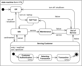 State Diagram Atm Schematics Online

![]() Hierarchical State Machine Design Pattern
Hierarchical State Machine Design Pattern

 State Diagram For Login Page All Diagram Schematics
Sparxsystems Europe State Machine Diagram Wiring Diagram
 State Machine Diagram Uml 2 Tutorial Sparx Systems
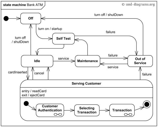 State Diagram Atm Today Wiring Schematic Diagram
 Uml Statechart Diagrams Tutorialspoint
 State Machine Diagram Uml 2 Tutorial Sparx Systems
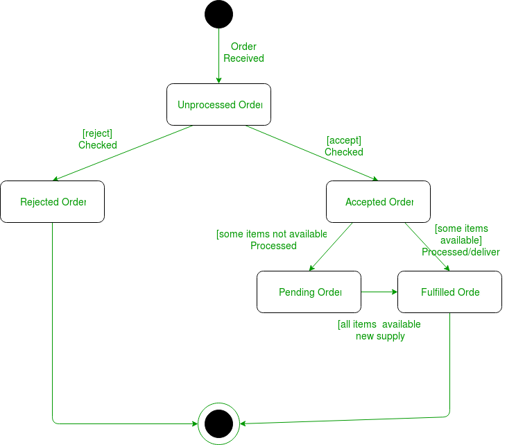 Unified Modeling Language Uml State Diagrams Geeksforgeeks

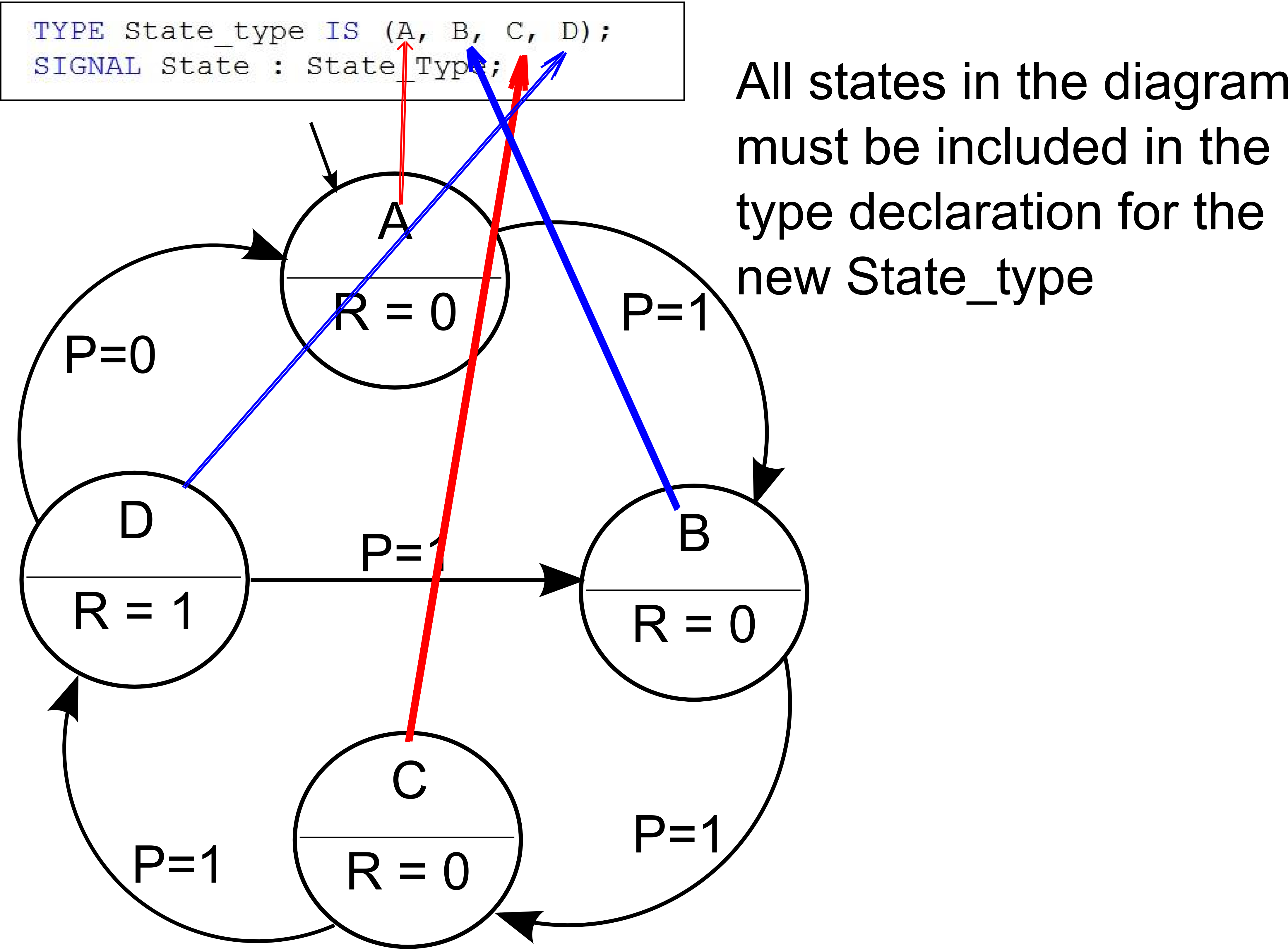 Implementing A Finite State Machine In Vhdl
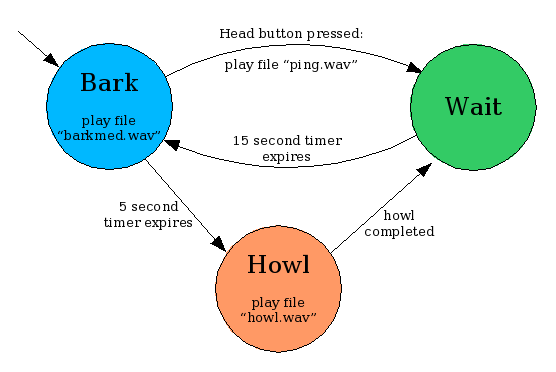 Exploring Tekkotsu Programming On Mobile Robots
 Fig 19 The Finite State Machine Simulator The State Diagram

State Machine Diagram Transition Notation
 Uml State Machine Diagrams Overview Of Graphical Notation
 The Complete Finite State Machine Diagram Wiring Diagrams Home
0 Response to "State Machine Diagram Tutorial"
Post a Comment