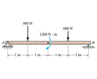
Draw The Shear Diagram For The Beam Follow The Sign Convention Figure 1
Downward shear force positive and upward shear force negative. Figure 1 click on add vertical line off to add discontinuity lines.
![]() Solved Consider The Beam Shown In Figure 1 Assume The
Solved Consider The Beam Shown In Figure 1 Assume The
Figure 1 click on add vertical line off to add discontinuity lines.
Draw the shear diagram for the beam follow the sign convention figure 1. 329 6 1 draw the shear and moment diagrams for shaft. Follow the sign convention. Follow the sign convention.
Follow the sign convention. And 2 draw the shear force and bending moment diagrams. 1 derive the shear force and bending moment equations.
Figure 1 click on add vertical line off to add discontinuity lines. Clockwise moment negative and anticlockwise moment positive. Follow the sign convention.
Follow the sign convention. Draw the moment diagram for the beam. Chapter 06 solution manual mechanics of materials mom structural axial shear and bending moments 329 6 1 draw the shear and moment diagrams for shaft draw the shear and moment diagram for beam board chapter 06 solution manual mechanics.
Problem 770 draw the shear diagram for the beam. Show transcribed image text part a draw the shear diagram for the beam. Part a draw the moment diagram for beam follow sign.
Then click on add segment button to add functions between the lines. Answer to problem 759 part a draw the shear diagram for the beam. Draw the shear diagram for the beam.
Neglect the weight of the beam. B draw the moment diagram for the beam. Follow the sign convention.
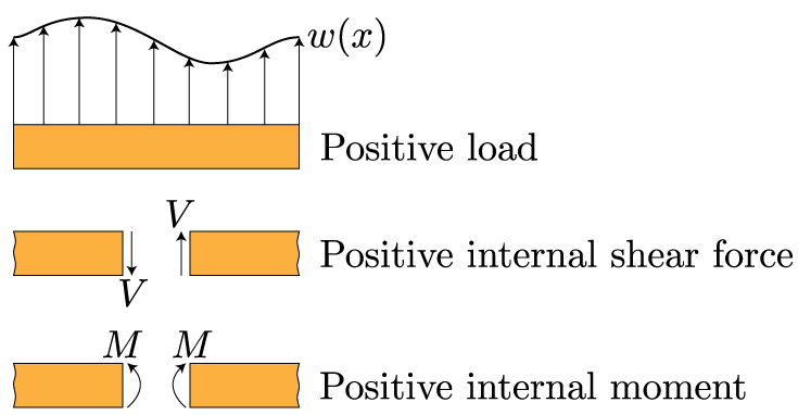
For drawing a bending moment diagram or bmd we use a positive sign for the sagging bending moment and a negative sign for the hogging bending moment as shown in the figure below. Then click on add segment button to add functions between the lines. Show transcribed image text problem 770 draw the shear diagram for the beam.
Follow the sign convention. Then click on add segment button to add functions between the note 1 you should not draw an extra discontinuity line at the point where the curve passes the x axis. Note 2 you should not draw an extra discontinuity line at the.
Note 1 draw a vertical line to denote local maximum or minimum. Figure 1 click on add vertical line off to add discontinuity lines. Solution note that the triangular load has been replaced by is resultant which is the force 05 12 360 2160 lb area under the loading diagram acting at the centroid of the loading diagram.
Figure 1 part b draw the moment d. Click on add vertical line off to add discontinuity lines. Follow the sign convention.
Figure 1 click.
 How To Draw Shear Force And Bending Moment Diagrams
 Beam Forces Moments Engineering Library
 For The Figure Below Draw A Draw The Shear Diagram For
 Structural Design For Non Structural Engineers
 How To Draw Shear Force And Bending Moment Diagrams
 Solved 1 Draw The Shear Diagram For The Beam Follow The
 Beam Reactions And Diagrams Strength Of Materials
 A A Draw The Shear Diagram For The Beam Follow
 Mechanics Of Materials Bending Normal Stress Mechanics
 Moment Area Method Example 3 Simply Supported Beam

 Structural Design For Non Structural Engineers
Structural Analysis
Mechanics Of Materials Chapter 4 Shear And Moment In Beams
Untitled
 Mech Ce6306 Som Notes
 Shear And Moment Diagram Wikipedia
 How To Draw Shear Force And Bending Moment Diagrams
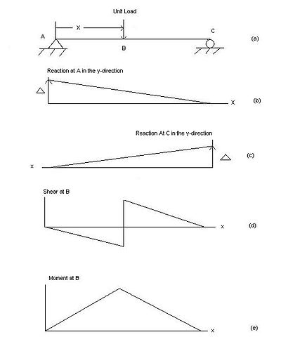 Influence Line Wikipedia
 Solved Problem 7 56 Part A Draw The Shear Diagram For The
 Derivation Of Stiffness Matrix For A Beam
 Solving Beam Bending Problems Using Singularity Functions
 Shear Force And Bending Moment Diagrams Wikiversity
Concept Of Fixed End Moments
 Beam Reactions And Diagrams Strength Of Materials
 Structural Design For Non Structural Engineers
 How To Draw Shear Force And Bending Moment Diagrams
0 Response to "Draw The Shear Diagram For The Beam Follow The Sign Convention Figure 1"
Post a Comment