Motor Control Wiring Diagram
Overcurrent protection for 3 wire control circuits 11 ac manual starters and manual motor. Wiring diagrams sometimes called main or construction diagrams show the actual connection points for the wires to the components and terminals of the controller.
 Single Phase Motor Contactor Wiring Diagram Elec Eng World
Three phase motor power control wiring diagrams 3 phase motor power control wiring diagrams three phase motor connection schematic power and control.

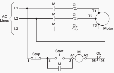
Motor control wiring diagram. Here i showed the forward reverse wiring diagram. In the diagram i connect the incoming three phase supply l1 l2 l3 to the mccb circuit breaker molded case circuit breaker. Basic wiring for motor control technical data.
The basic control circuits include two wire three wire controls manual automatic sequential control stopstart forward reverse and jogging circuits. If there are no convenient motor control circuit diagrams available for illustration you may want to ask a student to draw an across the line starter circuit on the whiteboard for everyone to see. Two wire control as seen in configuration 1 consists of a control device containing one set of contacts used to facilitate the on an off operation of a pilot device.
For example the start pushbutton we mentioned earlier has wires run to the device that contains the set of con tacts m in figure 14 and to contact points 2 and 3 in figure 16. Motor 3ct to 120 v separate control ot is a switch that opens when an overtemperature condition exists type mfo. Ac motor control circuits ac electric circuits.
Forward reverse motor control diagram for three phase motor for three phase motor forward reverse control circuit. In motor control circuits and how they relate to the symbols used in ladder diagrams and wiring diagrams. This book contains examples of control circuits motor starting switches and wiring diagrams for ac manual starters drum switches starters contactors relays limit switches and lighting contactors.
We use 2 magnetic contactors as forward reverse switch. Figure 17 figure 18. Wiring diagrams show the connections to the controller.
Wiring diagram book a1 15 b1 b2 16 18 b3 a2 b1 b3 15 supply voltage 16 18 l m h 2 levels b2 l1 f u 1 460 v f u 2. Wires between m1 control contact and control circuit broken open.


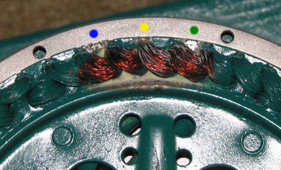
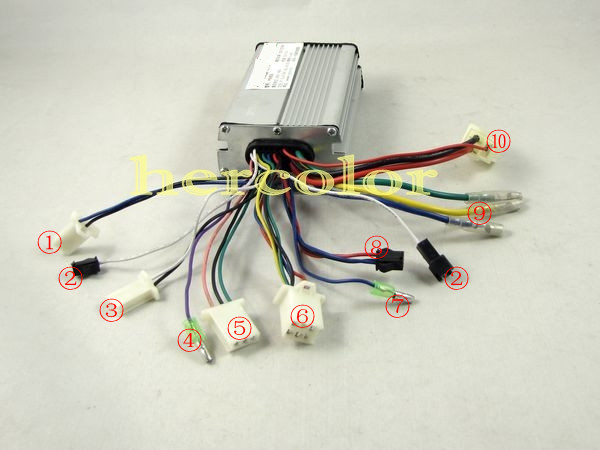
 Brushless Motors Bldc Motor Sensorless Motor Motor
 Basic Wiring For Motor Control Technical Data Guide Eep
Af2310 Radio Controlled Motor Circuit Design Project Circuit
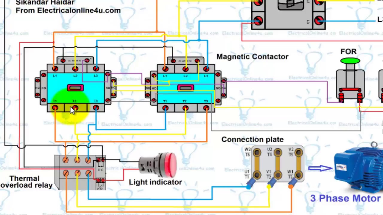 Forward Reverse Motor Control Wiring Diagram For 3 Phase Motor Urdu Hindi

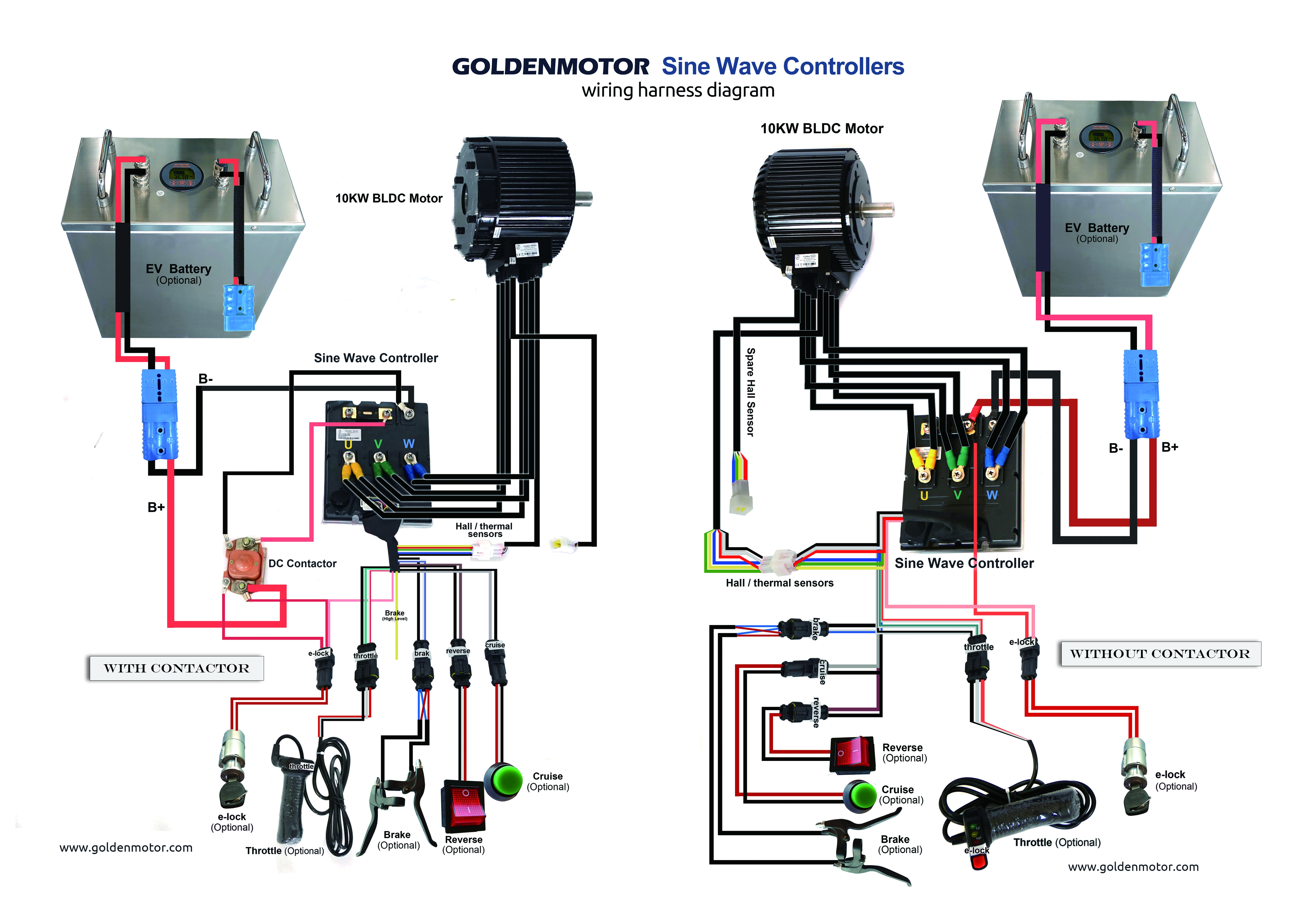
 Motor Wiring Diagram Wiring Diagram

 Wiring 3 Pole Contactor Wiring Diagram

 Allen Bradley Vfd Wiring Diagram Catalogue Of Schemas
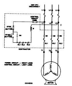
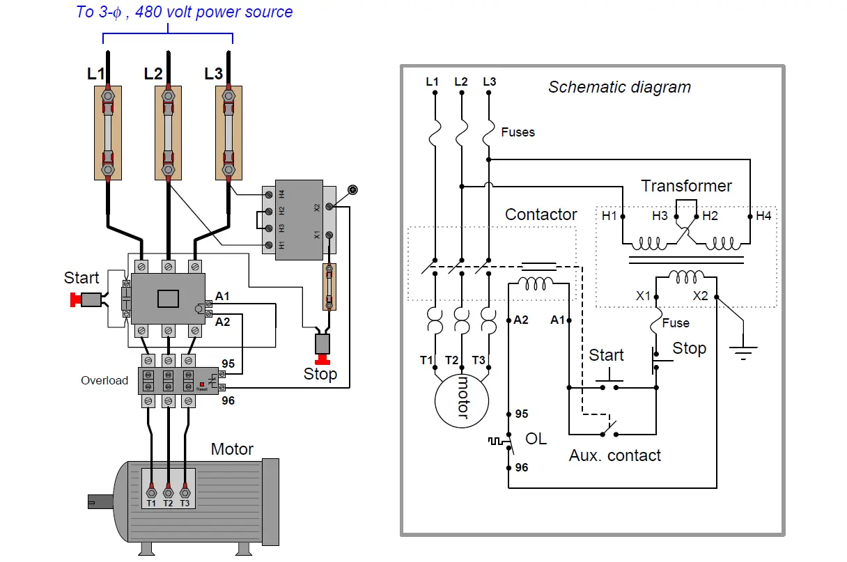
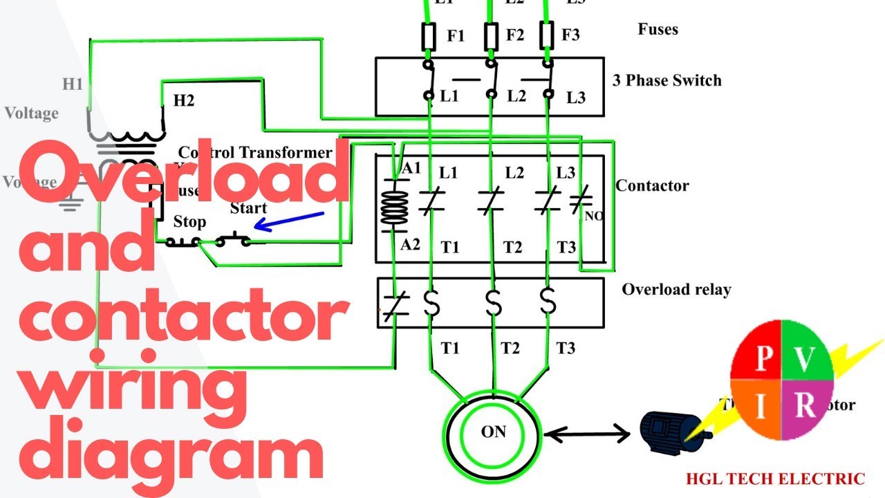
 Motor Starter Wiring Diagram Wiring Diagram

 Simple Motor Control Wiring Diagram Pdf Wiring Diagrams Folder
 Ac Motor Control Circuits Ac Electric Circuits Worksheets
 Smc Motor Wiring Diagram Technical Diagrams
 3 Phase Reversing Contactor Wiring Diagram Wiring Diagram
 A Three Pole Contactor Wiring Wiring Diagram


 Loco Wiring Hand Control Horn Relay Board 4qd
0 Response to "Motor Control Wiring Diagram"
Post a Comment