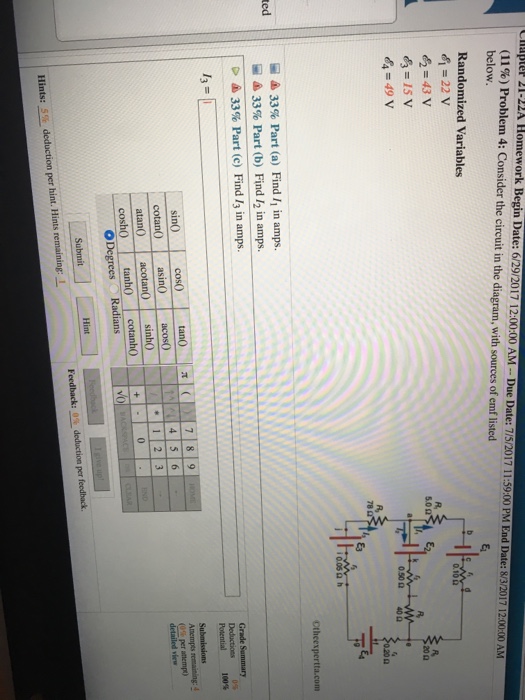
Consider The Circuit In The Diagram
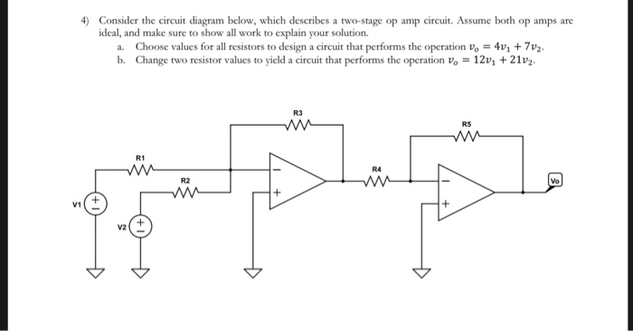
Given the circuit below calculate the equivalent resistance of the circuit. An amplifier circuit diagram consists of a signal pick up transducer followed by small signal amplifiers a large signal amplifier and an output transducer.
 Draw I O Energy Diagram For The Battery Faculty
Two 4 ω resistors in parallel is equivalent to a resistance of 2 ω.
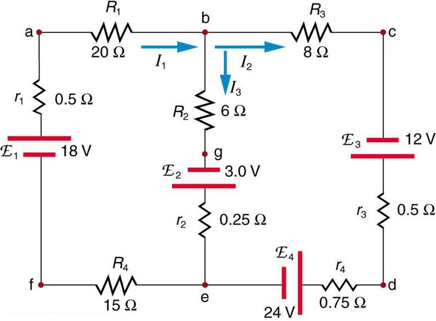
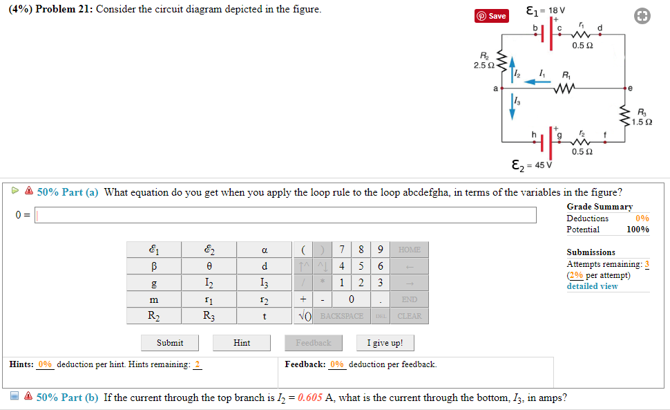
Consider the circuit in the diagram. Consider the following diagrams below. Then an understanding of the equivalent resistance of a series circuit can be used to determine the total resistance of the circuit. B if the current through the top branch is i2 0605 a what is the current through the bottom i3 in amps.
Voltage amplifier circuit and power amplifier circuit. More questions consider the circuit in the figure below in which v 95 v and r 4ohm. The diagram below shows a circuit with one battery and 10 resistors.
Consider the circuit in the figure below in which v 95 v and r 4. The power dissipated by each resistor. A find the current flowing through the 5 ω resistor.
Initially there are two type of amplifier circuit diagram is in practical ie. Diagram a represents a combination circuit with resistors r 2 and r 3 placed in parallel branches. 5 on the left and 5 on the right.
Calculate the current through the battery. B find the potential difference across the 3 ω resistor. Consider the following circuit diagram.
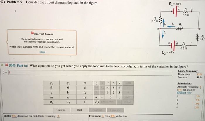
Consider the circuit diagram depicted in the figure. Determine the current through the voltage drop across and. Consider the two loads in the circuit below load brushless dc bldc motor with arduino part 2 circuit the circuit diagram below is a concept that should work with any microprocessor or a specialized driver ic that is able to produce the correct image for find the values of i and v for the circuits shown in the figure.
When hooked up to a certain battery there will be a current i moving to the right in the top wire above resistor a. A what equation do you get when you apply the loop rule abcdefgha in terms of the variables in the figure. We include additional resistors representing the resistance of the wire and then treat the wires in the diagram as ideal wires.
Consider the circuit shown.
 Consider The Following Circuit Diagram If R1 R2 R3 R4
Kirchhoff S Rules Physics
 Solved Consider The Circuit In The Diagram With Sources
 Consider The Following Figure Assume V 9 V R 1 2 2
 Solved Consider The Circuit Diagram Depicted In The Figur

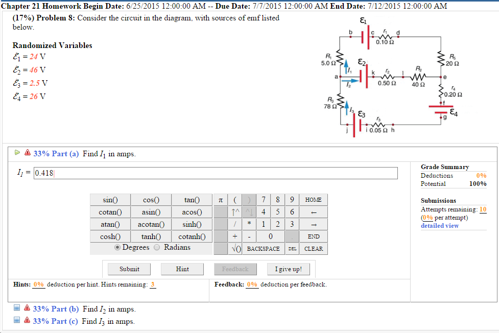 Solved Chapter 21 Homework Begin Date 6 25 2015 12 00 00
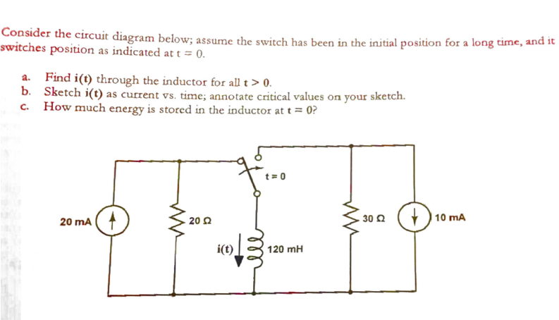 Solved Consider The Circuit Diagram Below Assume The Swi
 Consider The Circuit Shown In The Diagram Find The Current
 Gate2006 37 Gate Overflow
 4n25 Optocoupler Ic Pinout Specifications Equivalent Uses
 Consider The Following Circuit Diagram Youtube
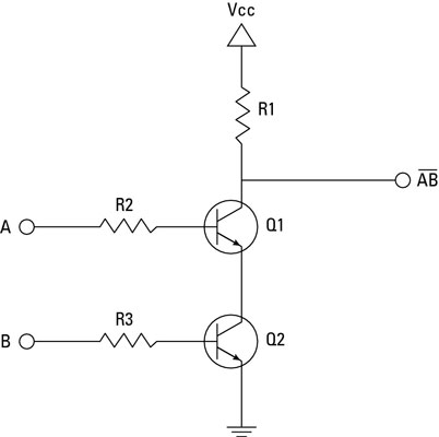
 In This Module You Will Learn What The Various Logic Gates
 Circuit Diagram Wikipedia
 Year 7 Circuit Diagrams Wiring Diagrams
Solved 600 3 6 K 6r This Is Problem 49 From Chapter 2 Of
 Two Amps Diagram Wiring Diagrams Folder
 Consider The Circuit Shown In The Figure Below In Which V
Circuit Diagram Let Us Consider The Lookup Table Function F
 Thevenins Theorem Tutorial For Dc Circuits
Sample Practice Exam 2012 Questions And Answers Midterm 2
 Grade 9 Circuit Diagram Problems Wiring Diagrams
0 Response to "Consider The Circuit In The Diagram"
Post a Comment