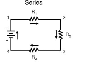
Diagram Of A Series Circuit
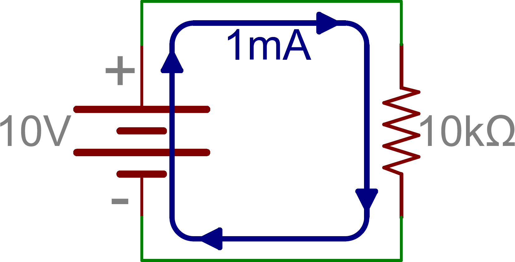
The amount of current in a series circuit is the same through any component in the circuit. In a series circuit the current that flows through each of the components is the same and the voltage across the circuit is the sum of the individual voltage drops across each component.
 Simple Series Circuit Diagram Wiring Diagram Images Gallery
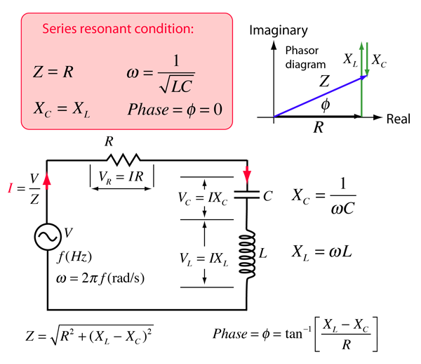
X t x l x c or x t x c x l whichever is greater.
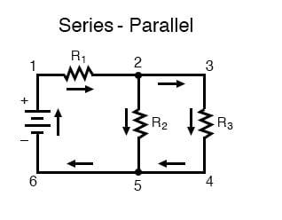
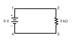
Diagram of a series circuit. This is because there is only one path for current flow in a series circuit. Equivalent resistance of resistors in series. Voltage applied to a series circuit is equal to the sum of the individual voltage drops.
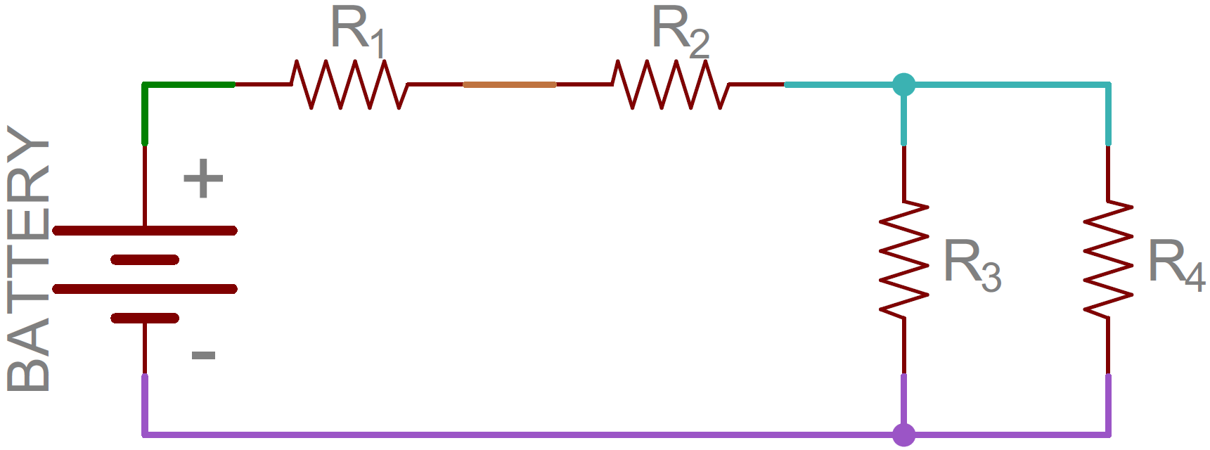
R r 1 r 2 r 3. A series circuit is the simplest type of circuit. The current is the same through each resistor.
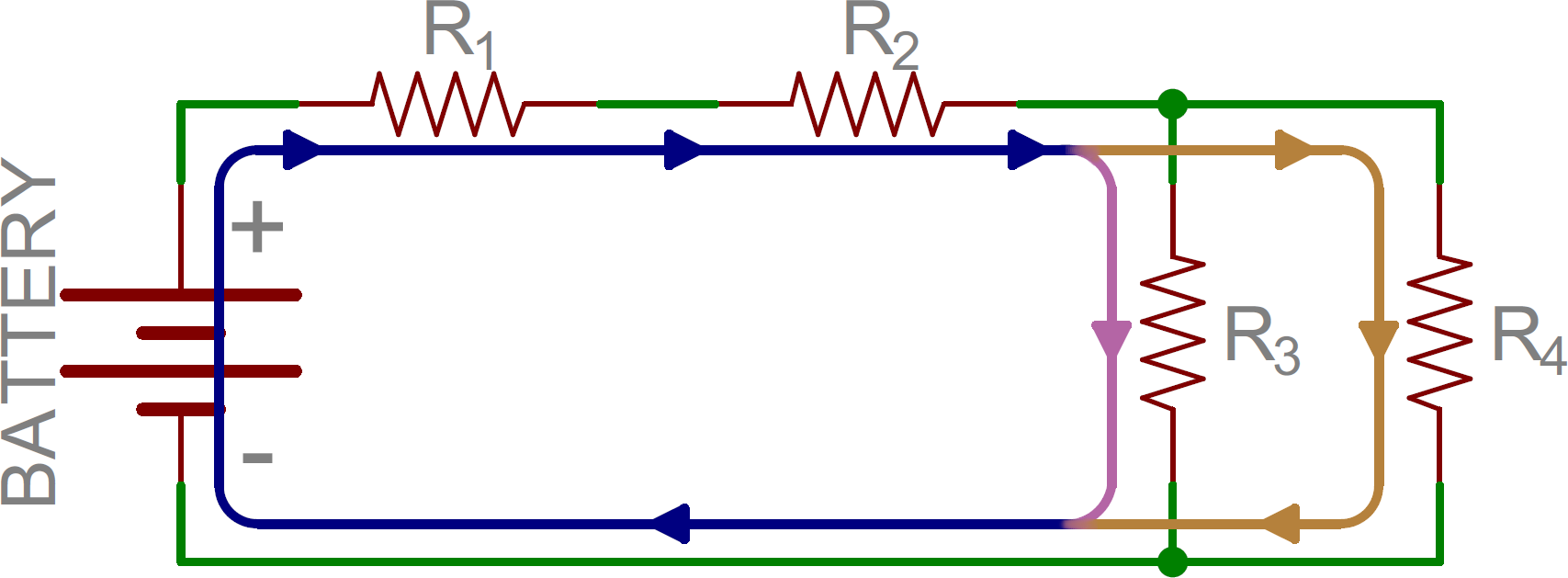
Thus the total impedance of the circuit being thought of as the voltage source required to drive a current through it. A series circuit is a circuit in which resistors are arranged in a chain so the current has only one path to take. The electrical charge leaves the positive terminal of the power supply passes through each resistor or other components in turn then returns to the negative terminal.
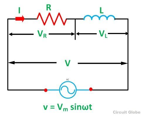
Then in the series rlc circuit above it can be seen that the opposition to current flow is made up of three components x l x c and r with the reactance x t of any series rlc circuit being defined as. Voltage drop in resistance vr ir is taken in phase with the current vector. Each charge passing through the loop of the external circuit will pass through each resistor in consecutive fashion.
A single loop with no branching paths. Because electric charge flows through conductors like marbles in a tube the rate of flow marble speed at any point in the circuit tube at any specific point in time must be equal. In a parallel circuit the voltage across each of the components is the same and the total current is the sum of the currents flowing through each component.
The vector sum of the two. Phasor diagram of rc series circuit take the current i rms value as a reference vector. A single cell light bulb and switch are placed together in a circuit such that the switch can be opened and closed to turn the light bulb on.
Use circuit symbols to construct schematic diagrams for the following circuits. Voltage drop in capacitive reactance vc ixc is drawn 90 degrees behind the current vector. The defining characteristic of a parallel circuit is that all components are connected between the same set of electrically common points.
If the circuit is broken at any point no current will flow. The voltage drop across a resistor in a series circuit is directly proportional to the size of the resistor. In a series circuit each device is connected in a manner such that there is only one pathway by which charge can traverse the external circuit.
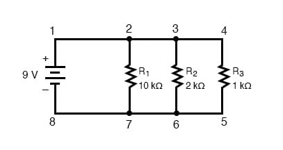
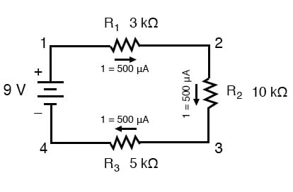
Looking at the schematic diagram we see that points 1 2 3 and 4 are all electrically common. So are points 8 7 6 and 5. The total resistance of the circuit is found by simply adding up the resistance values of the individual resistors.
 Electricity Circuits Symbols Circuit Diagrams
What Is The Difference Between A Series Circuit And A

What Are Series And Parallel Circuits Series And
 Series Circuits Series And Parallel Circuits Siyavula
 Series And Parallel Circuits Learn Sparkfun Com
 Series And Parallel Circuits Venn Diagram
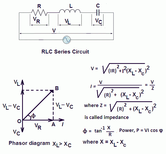 Rl Rc Rlc Series Circuits Your Electrical Guide
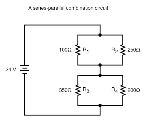 Parallel Circuit And Series Circuit Wiring Diagrams Home
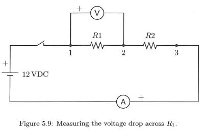 Solved Figure 5 9 Below Shows A Series Circuit With An
 Series Rlc Circuit And Rlc Series Circuit Analysis
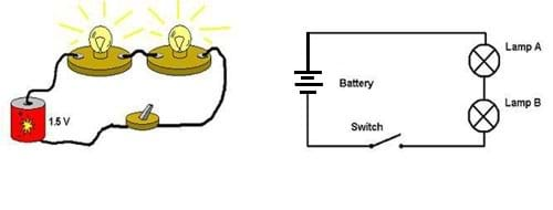 Circuits One Path For Electricity Lesson Teachengineering
 Simple Series Circuit Diagram The Best Place To Get Wiring
 Circuit Symbols Series Vs Parallel Circuits Diagram Quizlet
 Series Circuits Series And Parallel Circuits Siyavula

 What Are Series And Parallel Circuits Series And
 What Is Rl Series Circuit Phasor Diagram Power Curve
 Series And Parallel Circuits Learn Sparkfun Com
 A Series Circuit Diagram Wiring Diagram
 Series Circuit 5 Resistors Schematic Get Free Image About
 Series And Parallel Circuits Learn Sparkfun Com
 Direct Current Dc Electrical Circuits By Ron Kurtus
Resistors In Series And Parallel Circuitlab
 What Is A Series Circuit
 Series And Parallel Circuits Learn Sparkfun Com
0 Response to "Diagram Of A Series Circuit"
Post a Comment