High Resistance Grounding System Diagram
High resistance grounding ieee standard 142 1991 defnes high resistance grounded system as follows. The five pole disconnect switch three phases neutral to grounding resistor and neutral to sensing resistor will be equipped with properly sized fuses class cc.
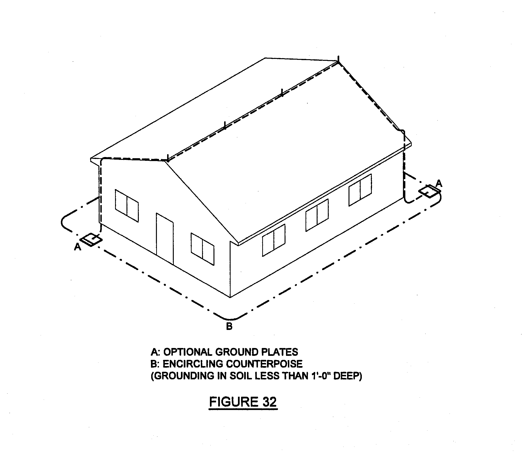
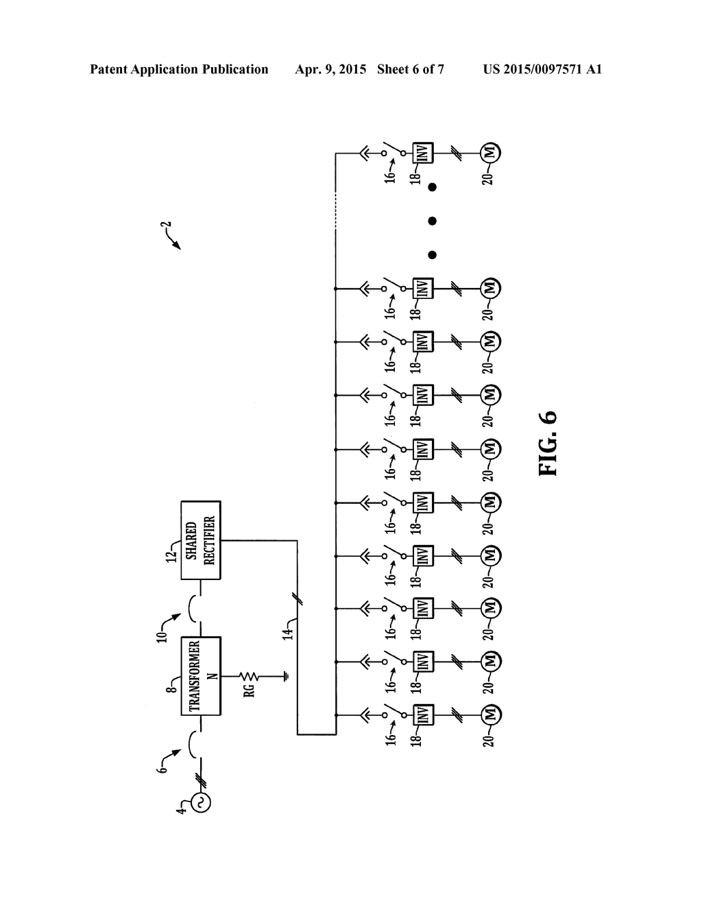
Figure 4 resistance grounded system.

High resistance grounding system diagram. 53 the high resistance neutral grounding equipment will contain the following equipment on the front of the unit as standard. Also capacitive charging current is not large enough to compensate the same so earth fault current is likely to be excessive. This level of current is commonly thought to be a 10 a or less.
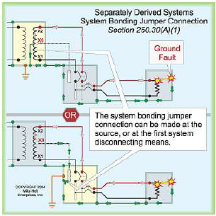
Provides an immediate indication of the first system ground. High resistance grounding system grounds the neutral through a resistance which limits the ground fault current to a value equal to or slightly greater than the capacitive charging current of that system unearthed neutral. High resistance grounding of the neutral limits the ground fault current to a very low level typically from 1 to10 amps and this is achieved by connecting a current limiting resistor between the neutral of the transformer secondary and the earth ground and is used on low voltage systems of 600 volts or less under 3000 amp.
This provides the continuity of service associated with ungrounded systems while reducing the high transient over voltages associated with them. High resistance grounding eatons high resistance grounding solutions allow for continuous operation and increased safety during fault conditions. In the event that a ground fault condition exists the hrg typically limits the current to 5 10a though most resistor manufacturers label any resistor that limits the current to 25a or less as high resistance.
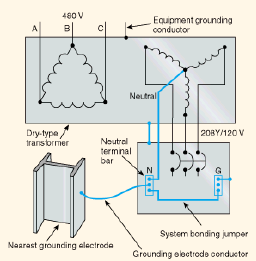
Provides ground fault detection and control of transient overvoltages during a single phase to ground fault on an ungrounded system thus minimizing the possibility of insulation failure in motors transformers power cables and electronic equipment. High resistance grounding mainly used in low voltage systems most common in 480 v and 600 v systems this arrangement means that a certain resistance has been intentionally put between the neutral point of a system and earth ground. A grounded system with a purposely inserted resistance that limits ground fault current can flow for an extended period without exacerbating damage.
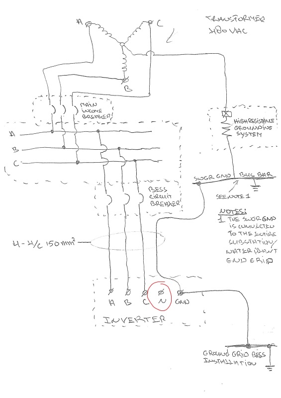
Provides a high resistance ground connection for a 480 volt three phase power system. High resistance grounding hrg systems limit the fault current when one phase of the system shorts or arcs to ground but at lower levels than low resistance systems. In case of mv system 33kv onwards to 33kv voltage between phase and earth is high.
Grounding systems perform the following functions. Hence resistance is connected between neutral to ground connection.
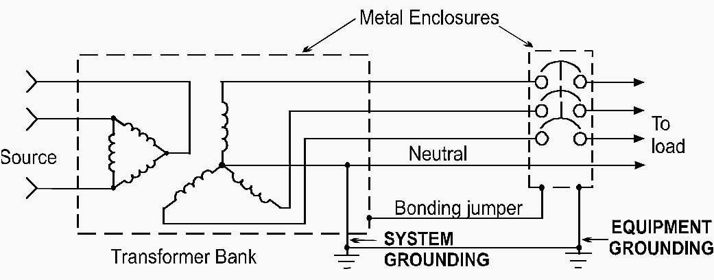
 Grounding And Bonding Of Electrical Systems Help Ez Pdh Com
 Substation Neutral Earthing Ee Publishers
![]() Grounding Transformer Wikipedia
Grounding Transformer Wikipedia
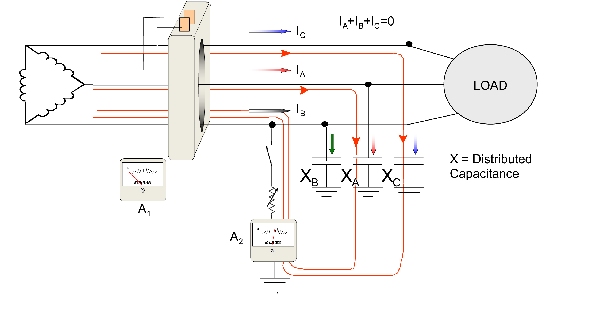
 Figure 1 From Identifying Ground Fault Location In High
Grounding Methods And Its Advantages Electrical
 Figure 13 From Selective High Resistance Grounding System
 Monitor Ground Fault Leakage Currents Electrical
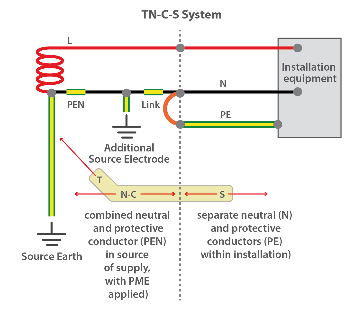 Getting Down To Earth Earthing Explained Gses
 What Is The Main Reason Of Using Ngr In A Power Transformer
![]() Ground Faults In Ungrounded Systems Risks Detection Eep
Ground Faults In Ungrounded Systems Risks Detection Eep
 Single Wire Earth Return Wikipedia

 What Is Grounding And Why Do We Ground The System And Equipment
Guideline For Neutral Earthing Part 3 Hrng
E Scheme Of The High Resistance Grounding System Ground
 Getting Down To Earth Earthing Explained Gses
 Wazipoint Engineering Science Technology How Ensure
 Neutral Required On 480 Vac System Electric Power
 Generator High Resistance Grounded And System Low Resistance

 Transformer Grounding Point Z4e
 Grounding And Bonding Of Electrical Systems Help Ez Pdh Com


0 Response to "High Resistance Grounding System Diagram"
Post a Comment