Bluetooth Transmitter And Receiver Circuit Diagram
The schematic of fm transmitter is given below. Ir receiver circuit diagram.
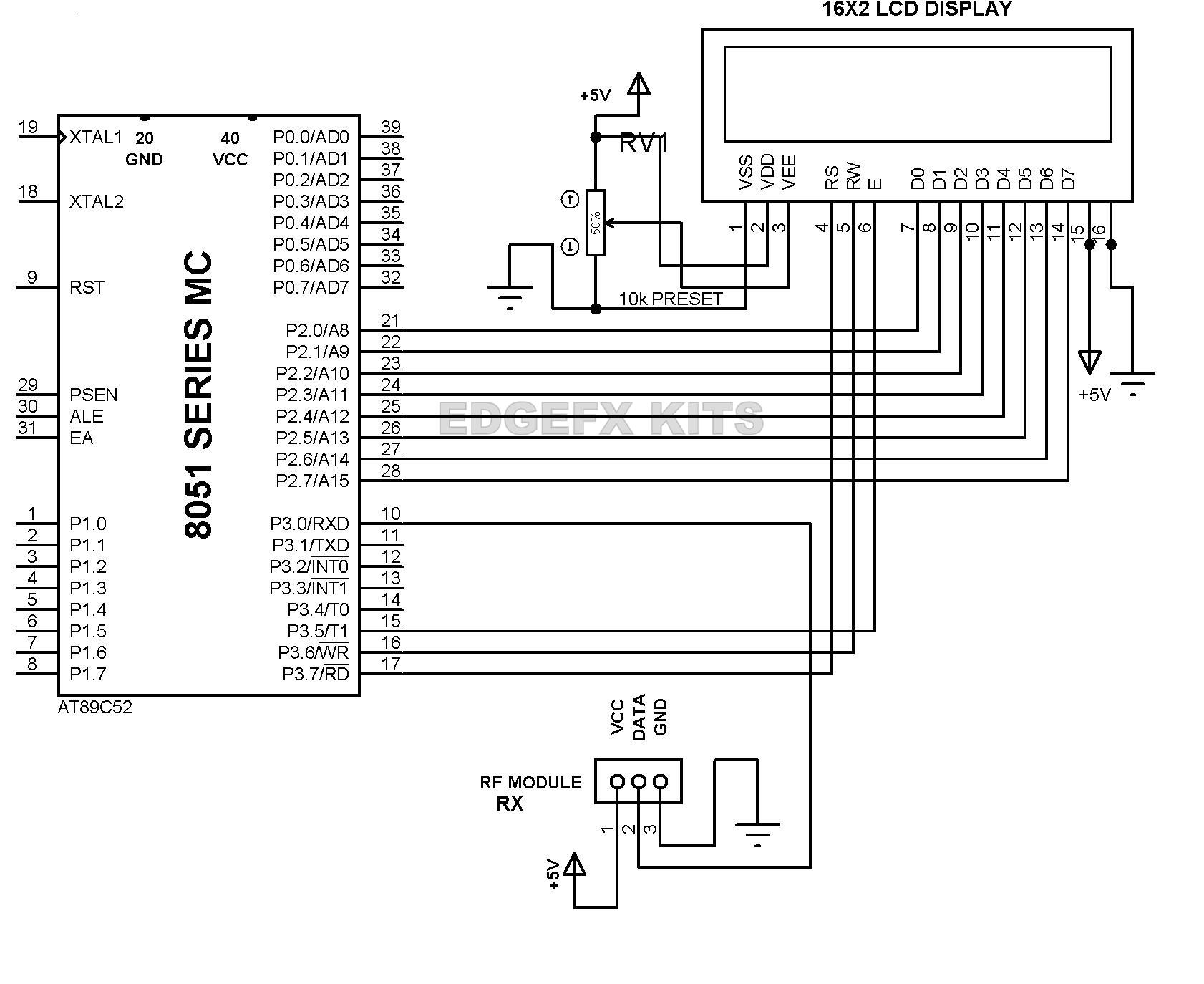
 Wireless Transmitter And Receiver Using Ask Rf Module
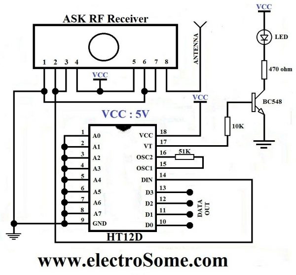
Wireless transmission can be done by using 433mhz or 315mhz ask rf transmitter and receiver modules.
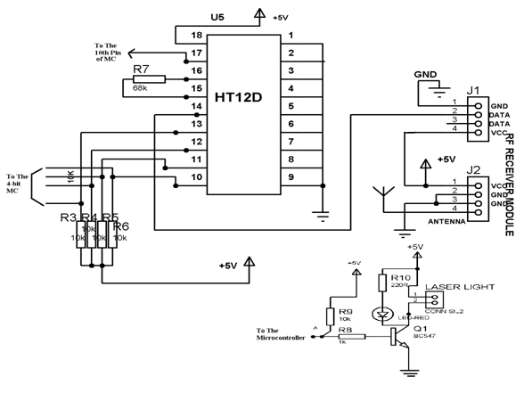
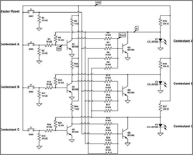
Bluetooth transmitter and receiver circuit diagram. As the physical standard it provides agreement with the radio frequency standard. The receiver section consists of rf receiver ht12d decoder ic and four leds. Bluetooth standards just like any other device bluetooth also requires a physical standard and a protocol standard.
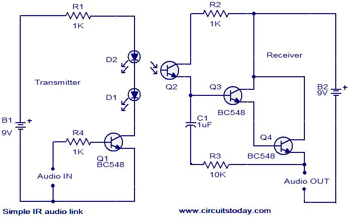
The circuit is divided into transmitter and receiver sections. But since infrared has a one to one technology the intended message sent by the transmitter will surely be received by and only by the receiver. We have use bc557 pnp transistor here to reverse the effect of tsop means whenever the output is high led will be off and whenever it detects ir and output is low led will be on.
Browse by manufacturer get instant insight into any electronic component. As you can see the rf transmitter circuit consists of the encoder ic and rf. How to make wireless rc carboathelicopter 4 channel rf transmitter receiver at home part 2diy duration.
Xbee modules are wireless communication modules which are built based on zigbee standard. You need the following components for this experiment. A wireless radio frequency rf transmitter and receiver can be easily made using ht12d decoder ht12e encoder and ask rf module.
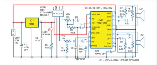
The transmitter section consists of an rf transmitter ht12e encoder ic and four push buttons. The output power requirement is 20 w rms 10 w rms per channel. Ir receiver circuit is very simple we just need to connect a led to the output of the tsop1738 to test the receiver.
In the schematic you will see the components required for making an fm transmitterthe transmission range of this circuit is approximately 10 20 meters. Before you proceed please see the schematic given below. Rf transmitter circuit rf receiver circuit.
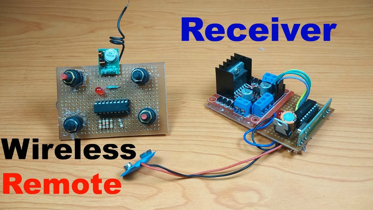
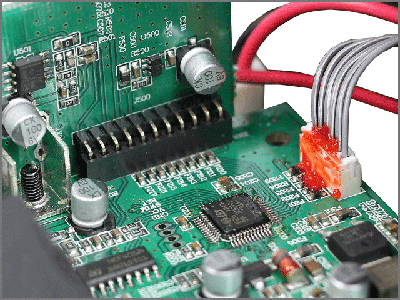
Bluetoothtransmitterreceivercircuitdiagram datasheet cross reference circuit and application notes in pdf format. And below ones showing the rf receiver circuit with breadboard setup. Rf transmitter and receiver circuit diagram working process output video.
What is xbee module. Try findchips pro for bluetoothtransmitterreceivercircuitdiagram. An extra led is connected to vt valid transmission pin of the decoder ic.
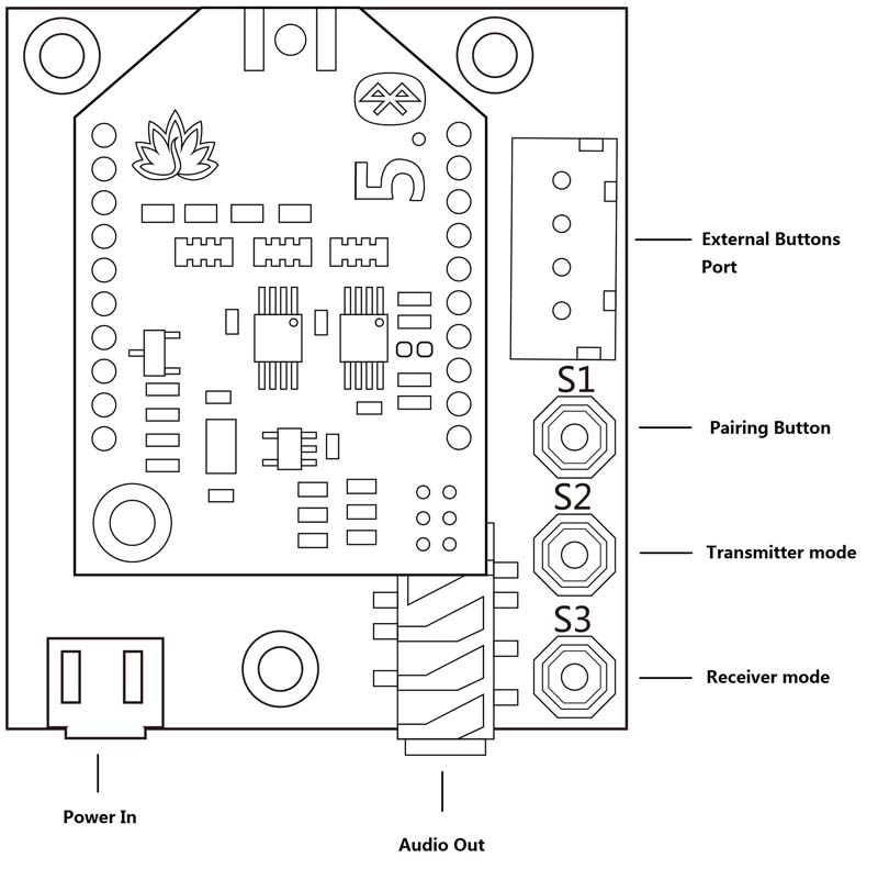
This wireless bluetooth stereo audio system based on a class d amplifier uses a bluetooth headset and external speakers. The complete circuit diagram including the transmitter and receiver part for this project is shown in the images below. Below pictures showing the rf transmitter circuit with breadboard setup.
Top results 6 part. Zigbee standards are standards with range between bluetooth and wifi. It utilizes the ieee 802154 protocol.
 Make Your Own Low Budget Bluetooth Music System 5 Steps

 Voice Transmitter Diagram Schematic Wiring Diagram
 Wireless Rf Module Rf Transmitter And Receiver Latest
![]() Wireless Tv Audio Transmitter
Wireless Tv Audio Transmitter
 Wireless Rf Module Rf Transmitter And Receiver Latest
![]() Tv Transmitter Circuit Diagram Wiring Diagram T1
Tv Transmitter Circuit Diagram Wiring Diagram T1
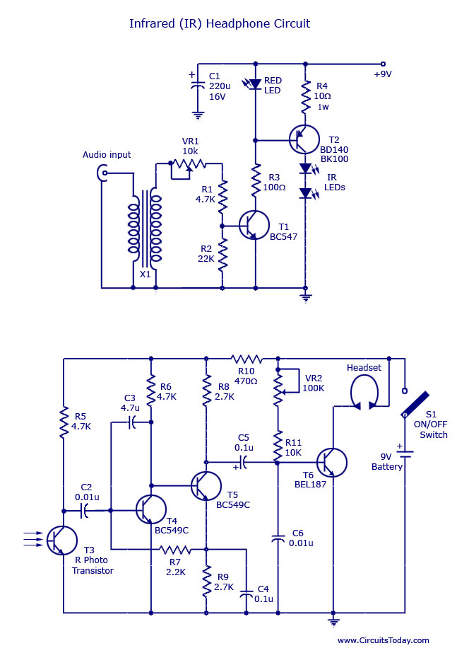
Ir Transmitter And Receiver Circuit Diagram
 Ir Receiver Circuit Diagram Elektronik In 2019
 Am Receiver Circuit Electroschematics Com
 Two Channel Wireless Audio Amplifier Using Bluetooth And
 Avantree Aptx Low Latency Wireless Transmitter And Receiver Set Bluetooth Audio Adapter Portable For Tv Headphones Speakers Camera Etc Plug
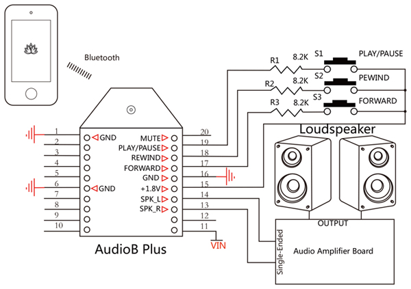 Audiob Plus Bluetooth Audio Receiver Module Apt X
 Bluetooth Circuit About Its Basic Introduction
 Tsa6175 Bluetooth 5 0 Multipoint Audio Receiver Apt X
![]() Bluetooth Transmitter Circuit Diagram Wire Management
Bluetooth Transmitter Circuit Diagram Wire Management
 Baskciry Wireless Bluetooth 5 0 Transmitter Receiver Mini
 Bluetooth Circuit About Its Basic Introduction
How To Make Wireless Rc Car Boat Helicopter 4 Channel Rf Transmitter Receiver At Home Part 2 Diy
 Fm Transmitter Circuit Usefull Electronic Circuit
![]() Rf Controlled Robot Project And Circuit Diagrams For Rf
Rf Controlled Robot Project And Circuit Diagrams For Rf
![]() Wireless Rf Module Rf Transmitter And Receiver Latest
Wireless Rf Module Rf Transmitter And Receiver Latest
![]() Rf Based 12 Bit Signal Transmitter And Receiver
Rf Based 12 Bit Signal Transmitter And Receiver
0 Response to "Bluetooth Transmitter And Receiver Circuit Diagram"
Post a Comment