4 Wire Transmitter Wiring Diagram
2 6 3 7 measuring current including 4 20 ma with a resistive. Hope this video is perfectly helpful for all those who.
![]() Example 4 20ma Thermistor Transmitter Wiring Diagram
Example 4 20ma Thermistor Transmitter Wiring Diagram
We have covered 4 wire transmitter 3 wire transmitter and 2 wire transmitter.

4 wire transmitter wiring diagram. The corresponding transmitter may be found elsewhere in this website. The transmitter produces a distinctive tone which alternates between 2100 hz and 2200 hz. This is the 4 wire pressure transducer wiring diagram.
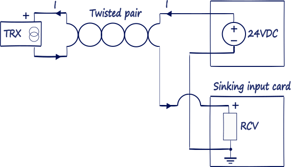
Type 4 refers to a 4 wire transmitter where the transmitter and receiver float and separate power leads power the transmitter outside of the current loop. The 4 ma zero end current is sufficient to drive the internal circuitry of the transmitter and the current from 4 to 20 ma represents the range of the measured process variable. The schematic diagram below shows the wire transmitter configuration.
3 phase fan wiring wire center. Current source transmitter non isolated 3 wire current sink transmitter non isolated 3 wire fully isolated 4 wire two wire loop powered transmitters. These wiring options include.
This video demonstrates the wiring scheme of transmitters. The power supply and the instruments are usually mounted in the control room. The receiver device of a transmitterreceiver combination that will prove extremely handy when tracing the path of electrical wiring in a building or to locate a break in a wire.
Diagram 2 3 4 wire transmitter working principle and related problemstwo wire system three wire system four wire system refers to the output of a variety of analog dc current signal transmitter its working principle and structure of the difference rather than just refers to the transmitter wiring form. You can save this photographic file to your personal device. Several transmitter wiring options exist.
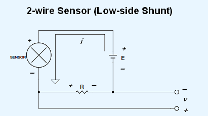
Instead a 2 wire transmitters circuitry is designed to act as a current regulator limiting current in the series loop to a value representing the process measurement while relying on a remote source of power to motivate current to flow. Please right click on the image and save the photo. Loop where the transmitter and receiver share a ground connection with power and the transmitter uses a third wire to connect to power outside of the current loop.
Check with the transmitter manufacturers to see that this. Here the transmitter is not really a current source in the sense that a 4 wire transmitter is. 4 3 2 output 4 20ma 1 output 4 20ma 120vac power 120vac power dc power supply transmitter 2 wire transmitter 2 wire 25 ma common 25 ma 25 ma common 25 ma 25 ma common 25 ma 25 ma common 7 7 6 5 4 3 2 1 output 4 20ma 4 20ma note.
4 20 ma transmitter wiring. We also have some more images associated to pressure transducer wiring diagram please see the picture gallery below click one of the. 4 wire transmitter of a graphic i get from the pressure transducer wiring diagram package.
The commons are connected together on the data logger. 4 20ma pressure transducer wiring diagram elegant viatran model. 4 wire transmitter wiring diagram collections of 3 wire pressure transducer wiring diagram wiring diagram collection.
The design of the associated control panel dictates which option should be used. So the first thing that came out was a four wire transmitterin other words two.
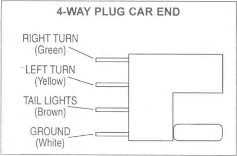
4 Wire Connector Diagram Wiring Diagram Directory
![]() 4 Wire Transmitter Wiring Diagram Catalogue Of Schemas
4 Wire Transmitter Wiring Diagram Catalogue Of Schemas
 All About Plc Analog Input And Output Programming
 Pressure Transmitter Circuit Diagram Wiring Diagram
 Xtr116 4 20ma Transmitter With 4 Wire Sensor Amplifiers
 Temperature Of A 4 Wire Transmitter Wiring Diagram Wiring
 42502 Wiring 2 3 And 4 Wire Transmitters To Flex Ex 1797
4 Wire Transmitter Wiring Diagram Beautiful Rtd Wiring
![]() 2 Wire Transmitter Wiring Diagram 1769 Oa16 Wiring Diagram
2 Wire Transmitter Wiring Diagram 1769 Oa16 Wiring Diagram
Temperature Of A 4 Wire Transmitter Wiring Diagram Wiring
3 Wire Ac Wiring Wiring Diagram Onlineplanet Analog
 What Is The Difference Between Two Wire And Four Wire

![]() 4 20ma Pressure Transducer Wiring Diagram Transmitter
4 20ma Pressure Transducer Wiring Diagram Transmitter
 What Is The Difference Between Two Wire And Four Wire
 3 Wire Transmitter Wiring Diagram Wiring Diagram
4 Wire Transmitter Wiring Diagram Technical Diagrams

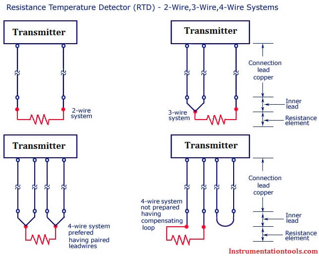
![]() 4 Wire Rtd Sensor Circuit Diagram Wiring Library
4 Wire Rtd Sensor Circuit Diagram Wiring Library
![]() 4 Wire Transmitter Wiring Diagram Free Wiring Diagram
4 Wire Transmitter Wiring Diagram Free Wiring Diagram
![]() 3 Wire 4 20ma Wiring Diagram Schematic Wiring Diagram
3 Wire 4 20ma Wiring Diagram Schematic Wiring Diagram
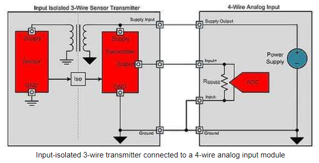
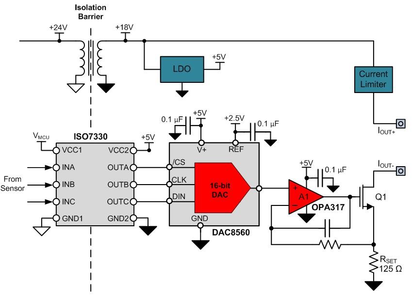 How To Design Fully Isolated 4 Wire Sensor Transmitters
0 Response to "4 Wire Transmitter Wiring Diagram"
Post a Comment