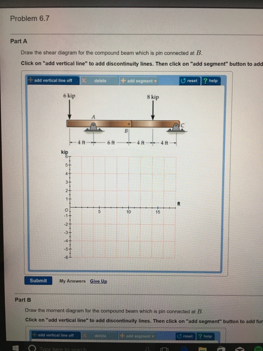
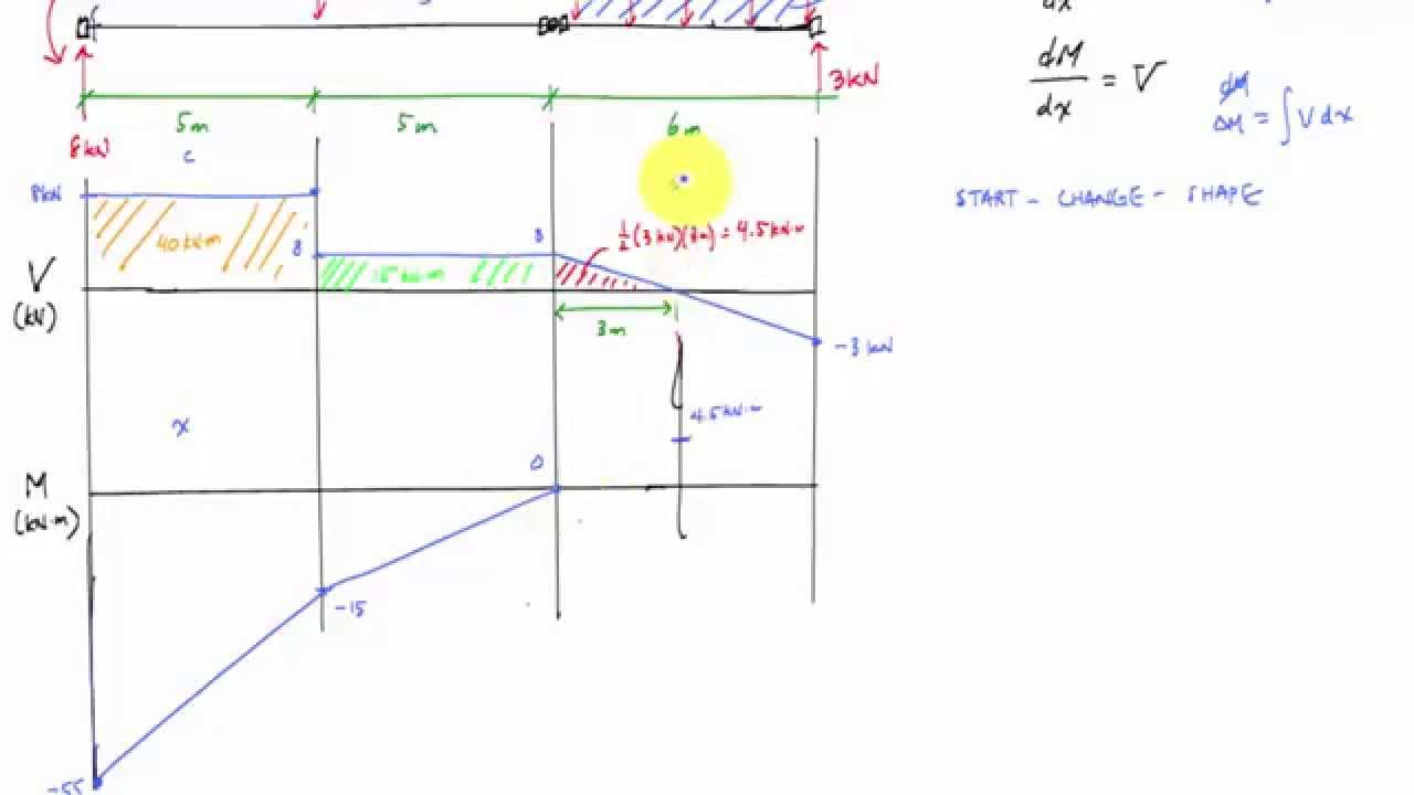
Draw The Shear Diagram For The Compound Beam Which Is Pin Connected At B
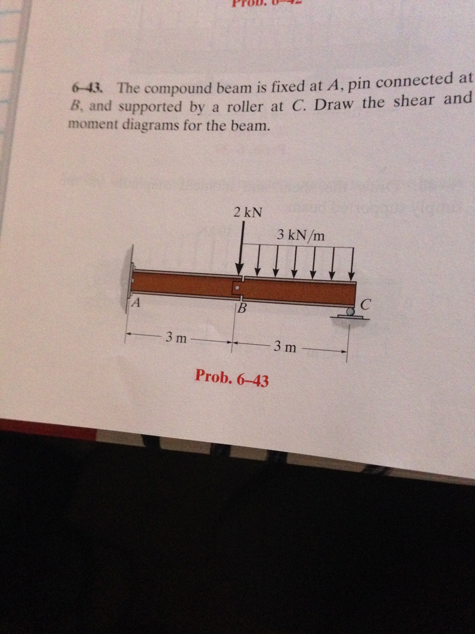
It is often necessary to draw shear and moment. The compound beam is fixed at a pin connected at b and supported by a roller at c.
329 6 1 Draw The Shear And Moment Diagrams For The Shaft
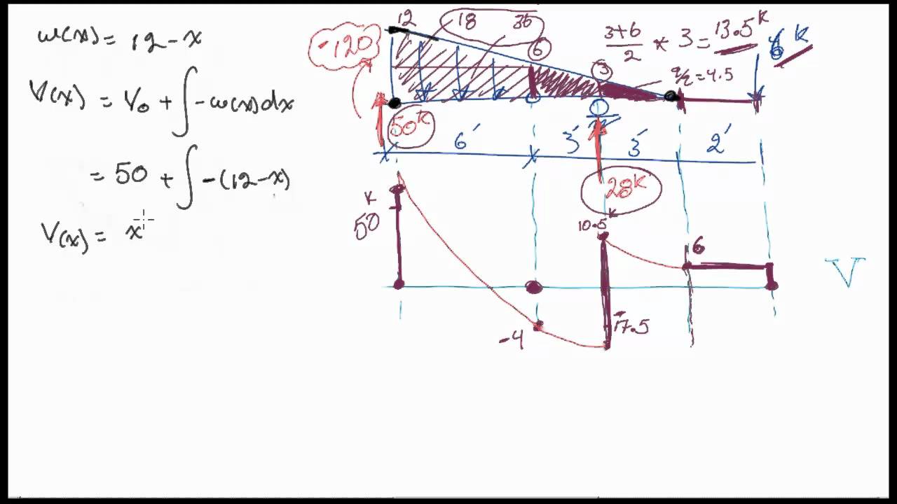
Draw the shear and moment.
Draw the shear diagram for the compound beam which is pin connected at b. 12 m 15 m12 m 8 kn 30 knm. Skip navigation sign in. Shear and moment diagrams for frames a frame is a structure composed of several members that are either fixed or pinconnected at their ends.
Draw the shear and moment diagrams for the compound beam shown in the figure. A b c 500 lbft 6 ft3 ft 7 solutions 44918 12709 1039 am page 610. The beam consists of two segments pin connected at b.
Assume the supports at a is fix c is roller and b is pin connections. Draw the shear and moment diagrams for the compound beam which ispin connected at b. Drawing shear force and bending moment diagram for a compound beam.
For beam with hinge mechanics of materials. No portion of this material may be reproduced in any form or by any means without permission in writing from the publisher. Draw the shear and moment diagrams for the beam.
Draw the shear and moment diagrams for the cantilever beam. The compound beam is fixed at a pin connected at b and supported by a roller at c. This problem has been solved.
700 lb 8 ft 4 ft 6 ft 9400 lbft 150 lbft v lb xft xft m lbft 1017 0 317 583 8 141 18 8 9400 1267 162 800 334 9 15. Posted one year ago the compound beam is fixed at a pin connected at b and supported by a roller at c. The compound beam is fix supported at a pin connected at b and supported by a roller at c.
The beam consists of two segments pin connected at b. Drawing shear force and bending moment diagram for a compound beam. Get more help from chegg get 11 help now from expert civil engineering tutors.
Draw the shear and moment diagrams for the beam. Draw the shear and moment diagrams for the simply supported beam. This video demonstrates drawing the internal shear and bending moment diagrams for a beam with a hinge.
Draw the shear and moment diagrams for the compound beam which ispin connected at b. Draw the shear and moment diagrams for the beam. Forces in beams beams various.
Draw the shear and moment diagrams for the compound beam shown in the figure. Draw the shear and moment diagrams for the beam. Draw the shear and moment diagrams for the beam.
Draw the shear and moment diagrams for the beam. Drawing the internal shear and bending.
 Hibbeler Statics Solution Chapter 7 1
 Hibbeler Statics Solution Chapter 7 1
329 6 1 Draw The Shear And Moment Diagrams For The Shaft
Solution
 Calculating Reactions For Beam With Hinge Statics Mechanics Example
 The Compound Beam Is Fixed At A Pin Connected At B And
 Draw The Shear Diagram For The Compound Beam Which Is Pin
Mechanics Of Materials Chapter 4 Shear And Moment In Beams
Chapter 06 Solution Manual Mechanics Of Materials Mom
 Solved The Compound Beam Is Fixed At A Pin Connected At
Problem 9 1 Two Beam Segments Ac And Cd Are Connected
 Shear Force And Bending Moment Diagrams For An Interesting Beam With A Hinge
329 6 1 Draw The Shear And Moment Diagrams For The Shaft
 Hibbeler Statics 12 Ed Cap 7 2
Hibbeler Statics 12 Ed Cap 7 2
329 6 1 Draw The Shear And Moment Diagrams For The Shaft

 Hibbeler Statics Solution Chapter 7 1
Mechanics Of Materials Chapter 4 Shear And Moment In Beams

329 6 1 Draw The Shear And Moment Diagrams For The Shaft
Untitled
329 6 1 Draw The Shear And Moment Diagrams For The Shaft
 Pdf Chapter 06 Andres Hernandez Academia Edu
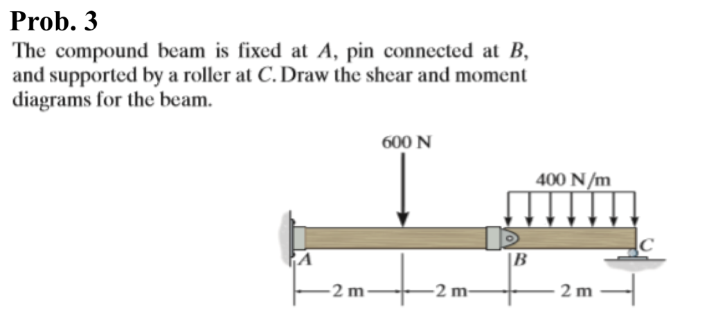 Solved Prob 3 The Compound Beam Is Fixed At A Pin Conne
 Shear And Moment Diagram For Beam With Hinge Mechanics Of Materials
 Hibbeler Statics Solution Chapter 7 1
0 Response to "Draw The Shear Diagram For The Compound Beam Which Is Pin Connected At B"
Post a Comment