Single Phase Ac Motor Speed Control Circuit Diagram
Figure 1 typical wiring diagram. Referring the circuit diagram of the proposed single phase closed loop ac motor controller the involved operations may be understood through the following points.
Three phase electrical wiring installation in home iec nec.
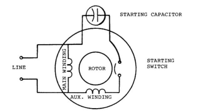
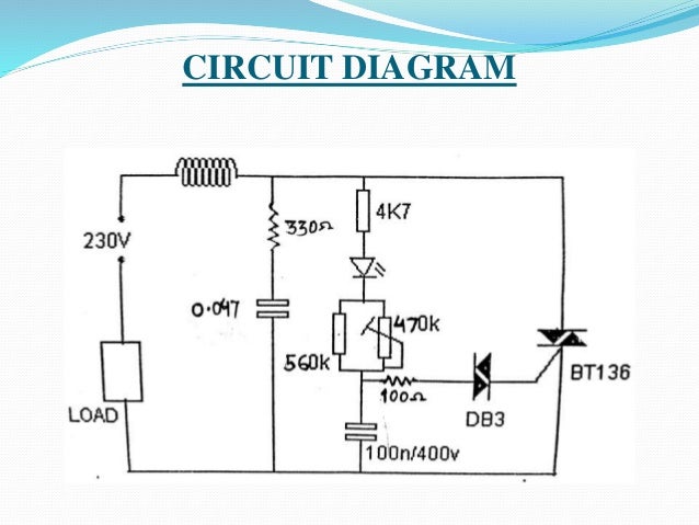
Single phase ac motor speed control circuit diagram. Basic wiring for motor control technical data. This triac based 220v ac motor speed controller circuit is designed for controlling the speed of small household motors like drill machines. Learn how a capacitor start induction run motor is capable of producing twice as much torque of a split phase motor.
Single phase ac motor speed controller december 22 2012 by a. Figure 1 is a typical wiring diagram for a three phase magnetic motor starter. The above diagram is a complete method of single phase motor wiring with circuit breaker and contactor.
In the above one phase motor wiring i first connect a 2 pole circuit breaker and after that i connect the supply to motor starter and then i do cont actor coil wiring with normally close push button switch and normally open push button switch and in last i do connection between capacitor. Also read about the speed torque characteristics of these motors along with its different types. The setting of p1 determines the phase of the trigger pulse that fires the triac.
A single phase induction motor is an electric motor that operates on a single waveform of alternating current. They can be used as a guide when wiring the controller. Wondering how a capacitor can be used to start a single phase motor.
Bhatt here is a very simple example of ac motor speed control given by changing firing angle of triac with the help of micro controller 89c2051. Click here to view a capacitor start motor circuit diagram for starting a single phase motor. The speed of the motor can be controlled by changing the setting of p1.
There are three types of single phase induction motors which are the shaded pole split phased and capacitor. Single phase induction motors are used in residential applications for ac motor appliances in single or multiple dwellings. For the positive half cycles of the input ac the capacitor c2 is charged through the resistor r1 and the diode d1.
Knowledge of basic single and three phase electrical systems including basic ac and dc motor control and safety. Multi speed 3 phase motor 3 speeds 1 direction power control diagrams one line diagram of simple contactor circuit.
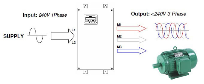
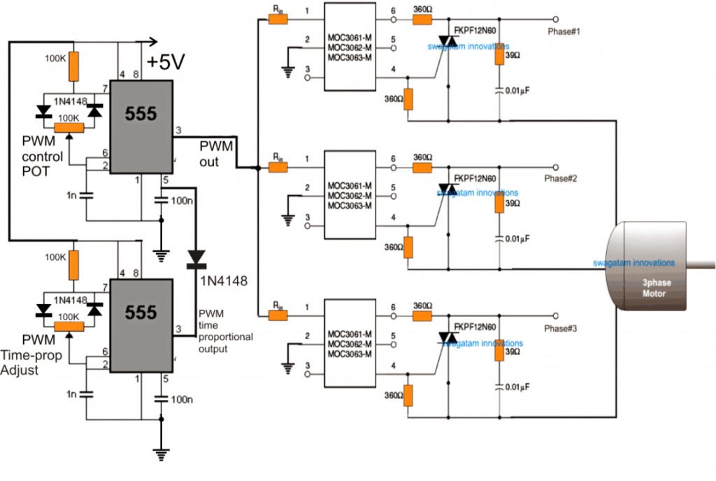
3 Phase Induction Motor Speed Controller Circuit Homemade
 Three Phase Motor Speed Control Circuit Diagram Wiring

 Ac Motor Speed Controller Circuit
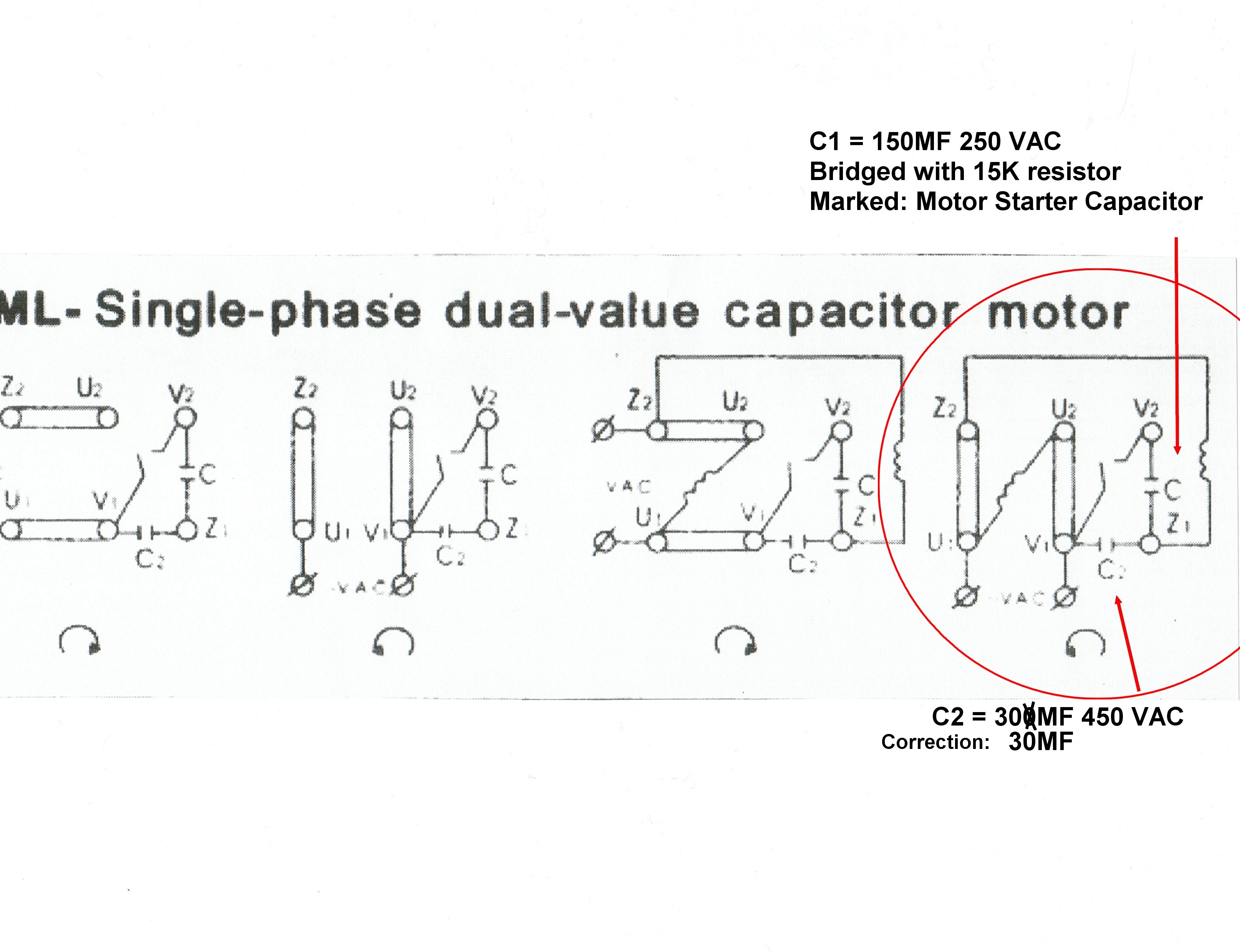
 Single Phase Ac Motor Diagram Amazing Wiring Diagram Product
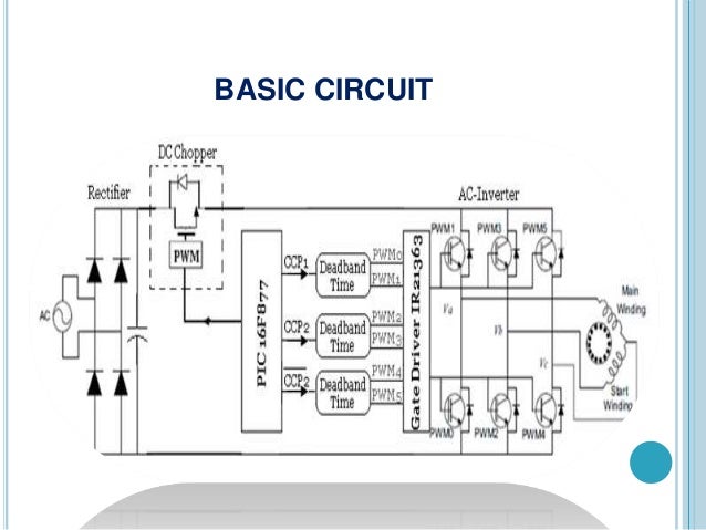
 Figure 2 From Pwm Ac Chopper Control Of Single Phase
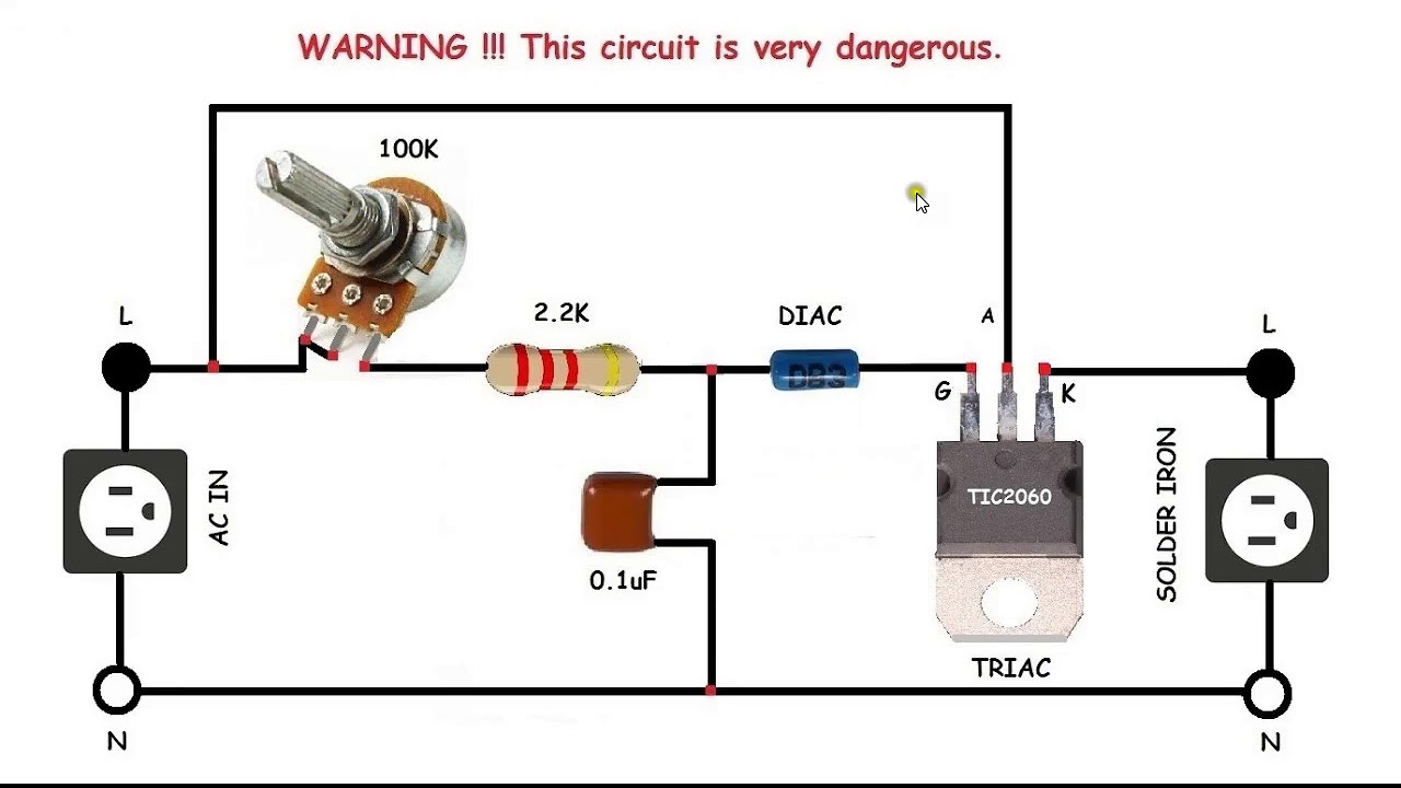 Ac Motor Speed Control Circuit How To Make Single Phase Motor Speed Control Circuit

Speed Control Of Single Phase Induction Motor By Android
Single Phase Ac Motor Diagram Catalogue Of Schemas
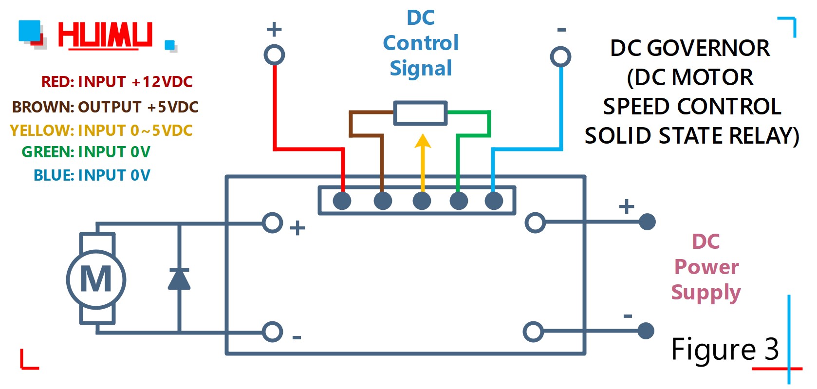
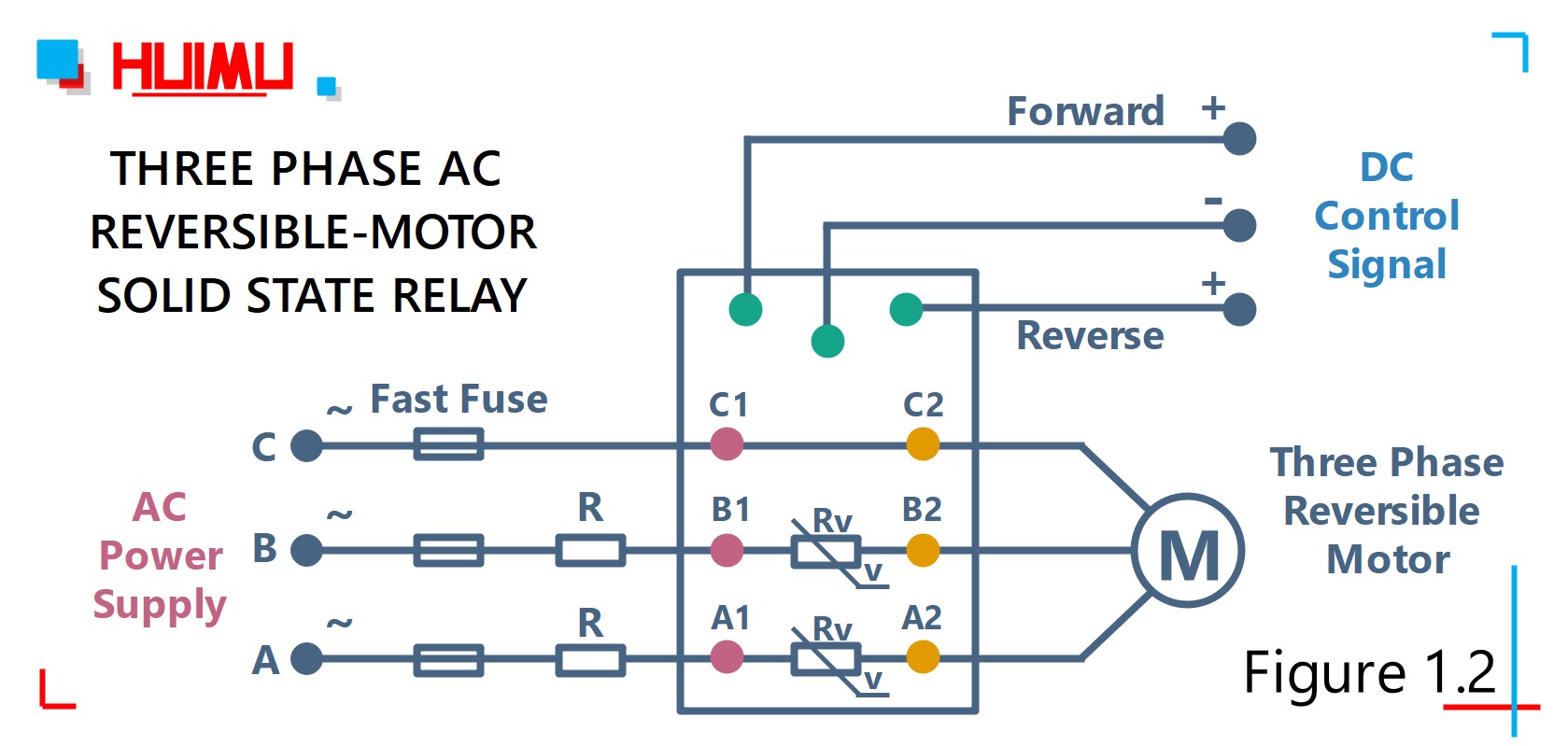 Motor Speed Or Direction Controller Solid State Relay Wiring
 Universal Motor Wikipedia

 Single Phase Induction Motors Electric Motor
 Motor Speed Or Direction Controller Solid State Relay Wiring


 Types Of Single Phase Induction Motor Split Phase
 Design Of Vfd For Speed Control In Single Phase Induction Motor
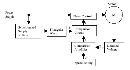
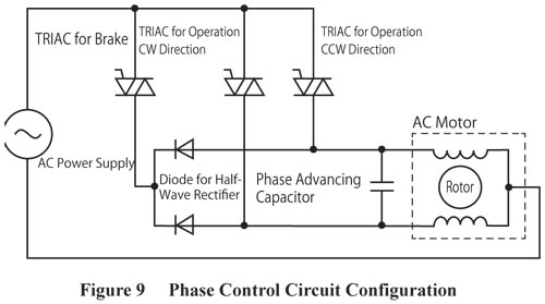 Ac Speed Control


 Speed Control Methods Of Various Types Of Speed Control Motors
 Efficient Single Phase Motor Speed Control Electrical
 Speed Control Of Single Phase Induction Motor
0 Response to "Single Phase Ac Motor Speed Control Circuit Diagram"
Post a Comment