Well Pump System Diagram
Aquatic filter systems 225223 views. The pump housing is a cylinder 35 in.
 Well Diagrams
Brass rope adapter section a connects the pitless adapter and the submersible pump.

Well pump system diagram. Tank has superior performance at depths to water to 70 ft. Best whole home well water filtration system what the epa recommends full oxidation platform 2019 duration. On pump installations a check valve installed near the tank inlet holds water in the tank when the pump is idle.
Jet pumps create suction in a rather novel way. An overview and description of typical residential well water system components. 3m heat shrink.
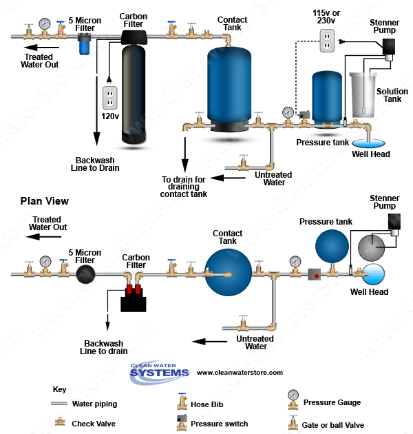
Taps are provided to accept pressure switch pressure gauge drain valve relief valve snifter valve etc. Some well water systems use a large storage tank to store the water before it is pumped again to the house. Ideal clamps section q all stainless steel clamps for dependable connections between pipe.
Proper pressure is maintained in the system by a pressure switch. Well diagram check valve section g located at the top of the pump it prevents backflow into. Diagrams typical pump installations the information provided here is for educational purposes only.
The aquapro 12 hp cast iron convertible jet pump the aquapro 12 hp cast iron convertible jet pump with 6 gal. Technically qualified personnel should install pumps and motors. Pressure switch well tank and other components explained.
Should be used on any system where the pump could develop pressure that exceeds the maximum system rating. In diameter and 24 ft long. Connects water line from pump to pressure tank and service line from tank to house.
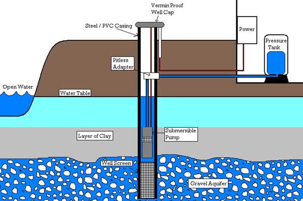
The pump is powered by an electric motor that drives an impeller or centrifugal pump. Most well water is pumped out of the ground automatically using a submersible pump or a jet pump that sits on top of the ground and draws water out of the ground to create water pressure for the home. Self priming after pump housing is initially filled.
The pump and the motor are contained in one housing submersed below the permanent water level within the well casing. When running the pump raises the water upward through the piping to the water tank. 18 pressure gauge measures water pressure in pressure tank.
The impeller moves water called drive water from the well through a narrow orifice or jet mounted in the housing in front of the impeller. 19 pressure switch signals the pump to start when the water system drops to a pre set low pressure and to stop when the high pressure mark is reached.
 Clean Well Water Report Well Pump Pressure Tank Diagram
 45 Shallow Well Jet Pump Installation Diagram Ei5a


 Well Pump Prices Well Pumps Commercial Water Well
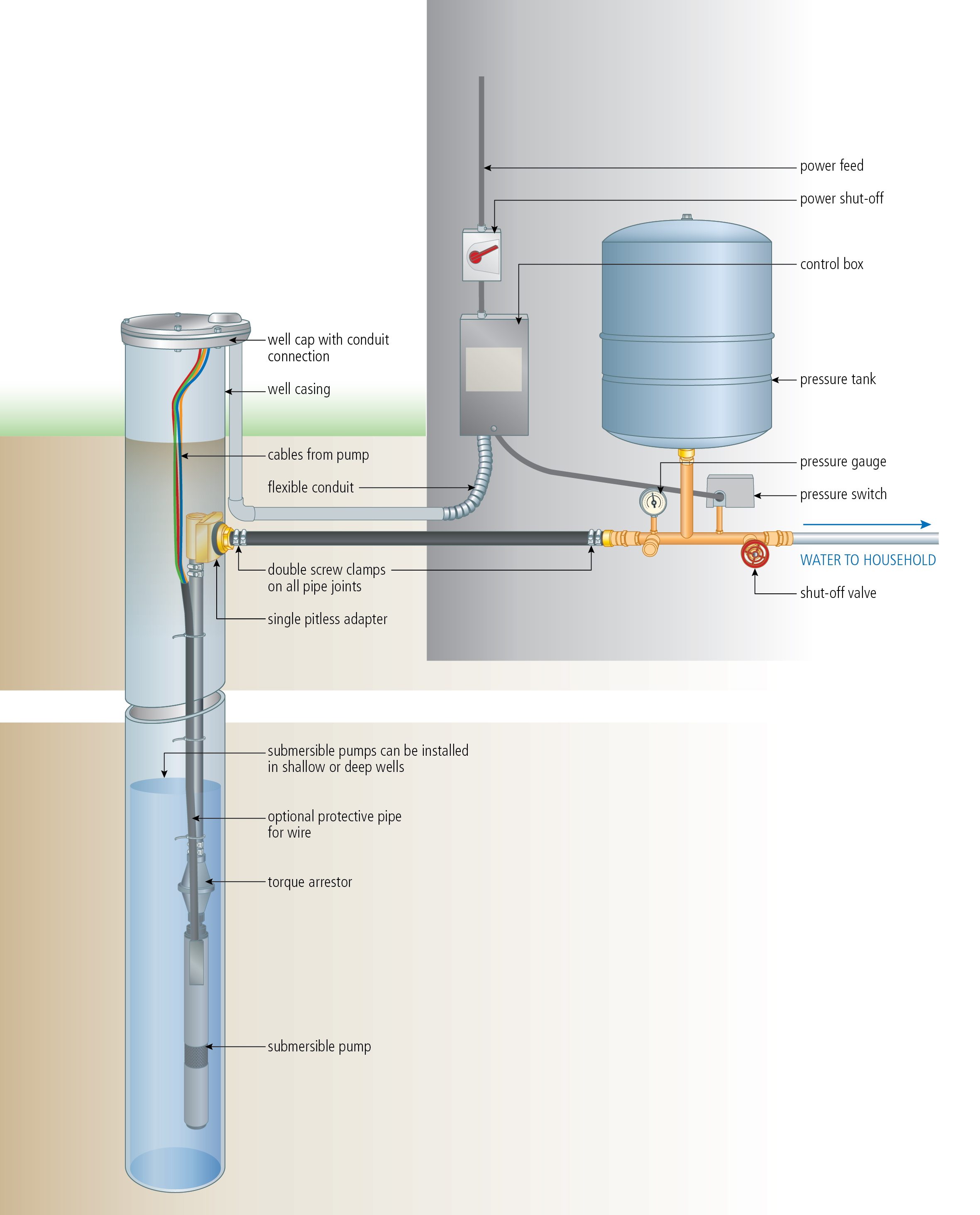 Install A Submersible Pump 6 Lessons For Doing It Right
 Shallow Well Jet Pump Installation Diagram Elegant Water
Well Pump Installation Diagram Wiring Diagram

Pin On Well Pump House

 Home Well Pump Wiring Diagram Catalogue Of Schemas
 Wiring Diagram As Well Water Distribution System Diagram On

 Deep Well Pressure Switch Wiring Diagram Pump Tank Under


 Submersible Well Pump Accessories Installation Diagram

 10 Best Well Pump House Images In 2014 Pump House

 Well Pump Diagram List Of Wiring Diagrams
0 Response to "Well Pump System Diagram"
Post a Comment