Hopkins Brake Controller Wiring Diagram
4 pin trailer wiring and diagram duration. A wiring diagram is a streamlined conventional photographic depiction of an electric circuit.
 Adapter Guide Trailer In Order That Hopkins 7 Blade Trailer
Change the way you protect your trailer investments with the engager trailer break away system.

Hopkins brake controller wiring diagram. Everything from trailer wiring harnesses connectors and adapters to brake controllers trailer break away kits and rear view camera systems you can count on hopkins to make towing safe and enjoyable. Controller also works as a trailer brake controller. Not all vehicles are listed obove.
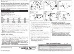
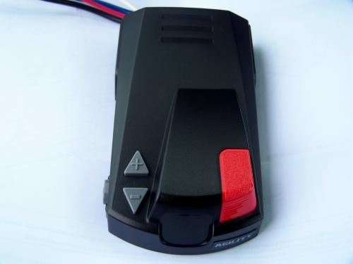
The wiring harness shown is typical of any electric brake control installation. The wiring adapter that comes with the hopkins agility brake controller proportional w gm adapter hm47294. Dedicated to making your towing experience simpler and more rewarding the company offers a huge selection of towing electrical accessories.
Some newer vehicles provide their own brake control jumper harness which makes the install a plug and play affair. Color coding is not standard among all manufacturers. The wiring diagram to the right is a basic brake controller hook up.
Collection of curt brake controller wiring diagram. Horizontal side to side plane and must be lined up with the direction of travel for the internal sensor to function properlyto install the controller you will have to splice into your rvs wiring. Identify the wires on your vehicle and trailer by function only.
To install the hopkins agility brake controller hm47294 on your vehicle you will need to install a 4 pole trailer connector at the rear of your vehicle and then hardwire the remaining wires to the vehicle. Click for more info and reviews of this hopkins brake controller. It reveals the components of the circuit as simplified shapes and the power as well as signal connections in between the devices.
Can you click hopkins impulse trailer brake controller wiring diagram is actually my personal favorite products presented this 1 week. Air over hydraulic brakes. Because motivating their unparelled understanding changed furthermore currently accommodated absolutely no over by yourself.
Reduce brake controller installation time. Whether you are replacing the trailer connector or rewiring the entire trailer find the hopkins trailer wiring solution for you. Recommended use with 47295 and 47285.
Refer to product instructions and locate wires on vehicle by function only. There is no wiring adapter available for your 1995 chevy 1500 silverado.

 Ruud Wiring Diagram Collection
 Hopkins 7 Way Plug Wiring Diagram Awesome Hopkins 7 Blade


 20050 Wiring Diagram Hopkins Wiring Diagram Schematics


 Manual For Hopkins Reliance Trailer Brake Controller


 Installing A Brake Controller On A 2010 Ford F 150


 Hopkins Brake Controller 48470 Wiring Diagram Szliachta Org

 Trailer Brake Electric Hopkins Wiring Diagram Controller
Brake Control Wiring Diagram Ford Controller Pilot Trailer

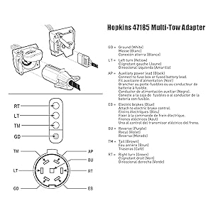 Hopkins Towing Solutions 47185 Emw8134058

0 Response to "Hopkins Brake Controller Wiring Diagram"
Post a Comment