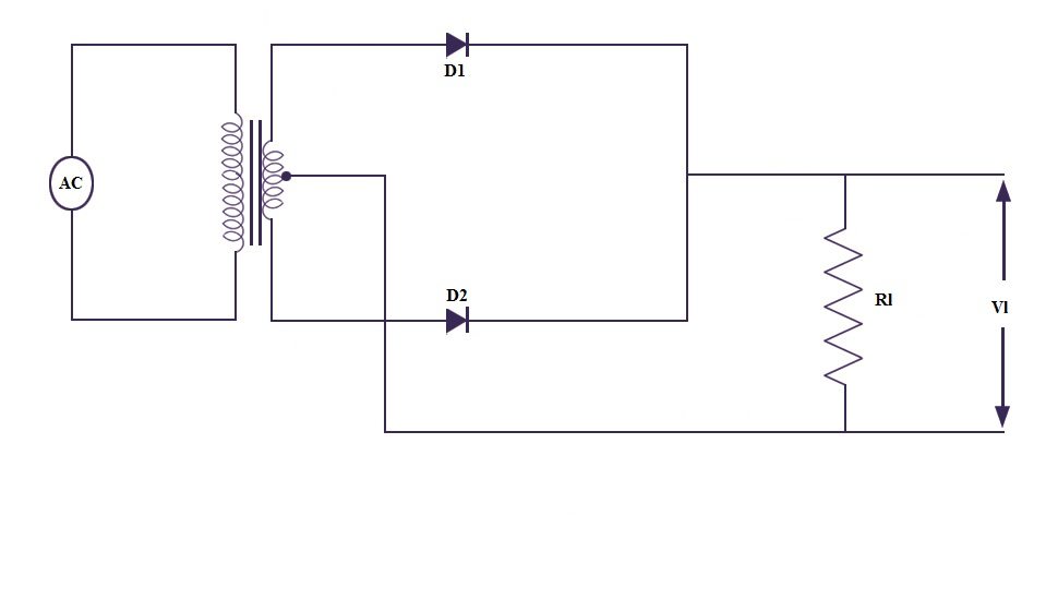
Full Wave Bridge Rectifier Diagram
The full wave bridge rectifier. The full wave bridge rectifier.
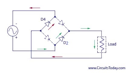
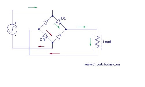
This single phase type of rectifier utilizes 4 individual rectifying diodes interfaced in a closed loop bridge configuration to generate the required output.
Full wave bridge rectifier diagram. Another type of circuit that produces the same output waveform as the full wave rectifier circuit above is that of the full wave bridge rectifier. It contains four diodes arranged in a bridge format and an ordinary step down transformer. This type of single phase rectifier uses four individual rectifying diodes connected in a closed loop bridge configuration to produce the desired output.
Using four diodes the bridge rectifier the circuit has a distinctive format with the circuit diagram based on a square with one diode on each leg. The type of circuit that gives the same output wave form as the full wave rectifier circuit given above is the full wave bridge rectifier. Full wave bridge rectifier circuit diagram is widely used in ac to dc converter and dc circuit designs this full wave rectifier called as bridge rectifier due to it shape.
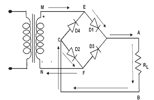
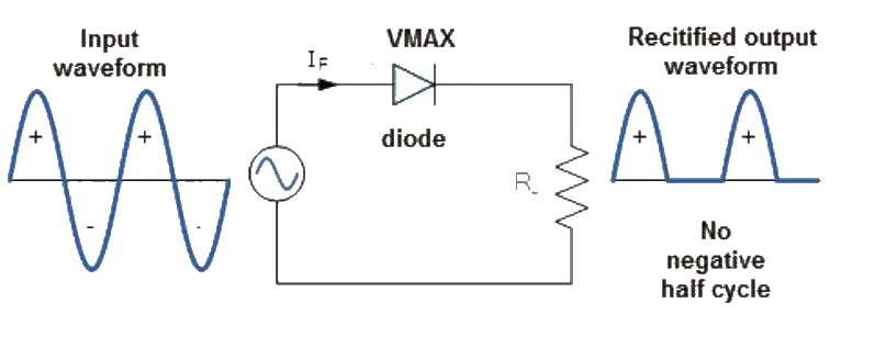
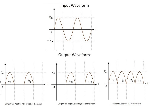
Full wave bridge rectifier circuit diagram with input and output wave forms during the first half cycle during the first half cycle of the input voltage the upper end of the transformer secondary winding is positive with respect to the lower end. Full wave bridge rectifier circuit with working explanation gallery of electronic circuits and projects providing lot of diy circuit diagrams robotics microcontroller projects electronic development tools. The bridge rectifier is widely used to provide full wave rectification and it is possibly the most widely used circuit for this.
 Four Diode Full Wave Bridge Rectifier
 Solved In Pspice Simulate A Full Wave Bridge Rectifier S
 Full Wave Rectifier Bridge Rectifier Schematic Learn
 Full Wave Bridge Rectifier Matlab Simulink
 Full Wave Rectifier And Bridge Rectifier Theory
 Full Wave Rectifier Circuit Diagram Center Tapped Bridge
 What Is A Rectifier Half Wave Full Wave Rectifier Theory
 Full Wave Bridge Rectifier Circuit Working And Applications

When A Sine Wave Of Peak Amplitude Of 10 V Is Rectified By A
Full Wave Bridge Rectifier Uncontrolled Working
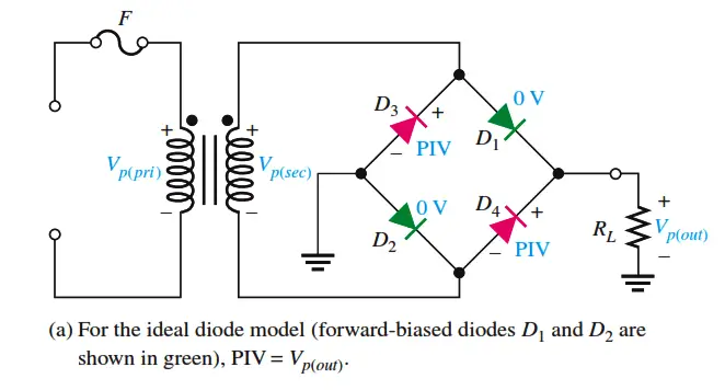 Full Wave Bridge Rectifier Peak Inverse Voltage

 Silicon Bridge Full Wave Rectifier Testing
 Doc Full Wave Bridge Rectifier Sourav Kumar Academia Edu
 Full Wave Rectifier Theory Circuit Working And Ripple Factor
 Electronic Circuits Full Wave Rectifiers Tutorialspoint
 Bridge Rectifier With Filter
 Full Wave Bridge Rectifier Multisim Live
 Bridge Rectifier With Filter
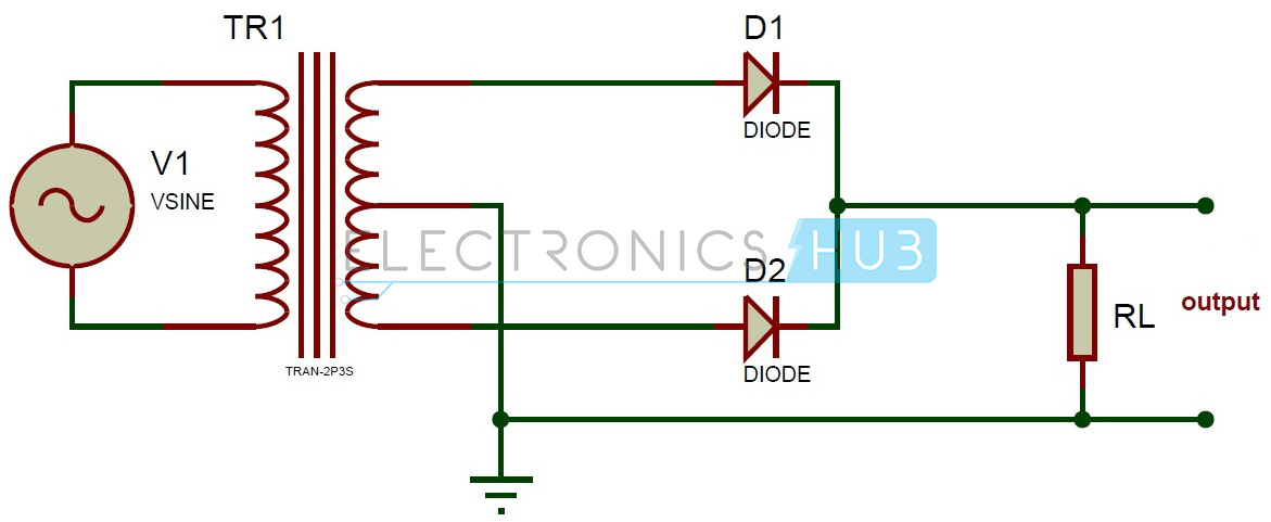
 Bipolar Output Full Wave Bridge Rectifier With Center Tapped
 Half Full Wave Rectifier Converting Ac To Dc Rectifier
 Full Wave Bridge Rectifier Operation With Capacitor Filter
0 Response to "Full Wave Bridge Rectifier Diagram"
Post a Comment