Single Phase Motor Connection Diagram
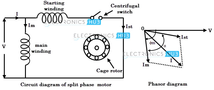
It shows the elements of the circuit as streamlined shapes as well as the power and signal links in between the tools. Learn how a capacitor start induction run motor is capable of producing twice as much torque of a split phase motor.

In the above one phase motor wiring i first connect a 2 pole circuit breaker and after that i connect the supply to motor starter and then i do cont actor coil wiring with normally close push button switch and normally open push button switch and in last i do connection between capacitor.
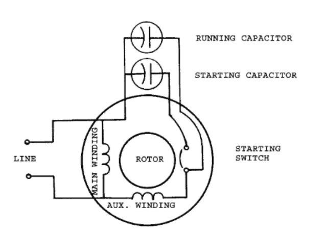
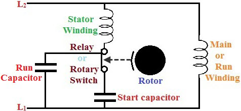
Single phase motor connection diagram. Click here to view a capacitor start motor circuit diagram for starting a single phase motor. Capacitor start capacitor run induction motors are single phase induction motors that have a capacitor in the start winding and in the run winding as shown in figure 12 and 13 wiring diagram. How to wire single phase motor with capacitor.
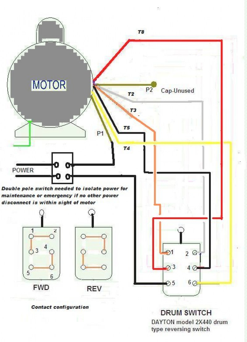
With single phase motor with capacitor forward and reverse wiring. Single phase motor wiring diagram with capacitor sources. Terminal markings and internal wiring diagrams single phase and polyphase motors meeting nema standards b.
Exico cannot be held responsible for a damage caused by incorrect wiring. You will find out how to identify to main and auxilliary winding and change motor rotation. Single phase motor wiring diagram forward reverse collections of phase meter wiring diagram single phase motor capacitor wiring.
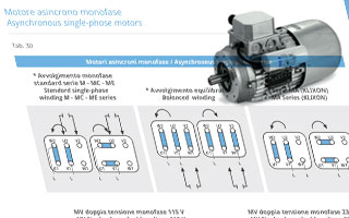
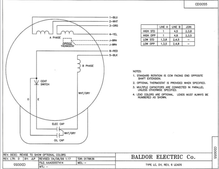
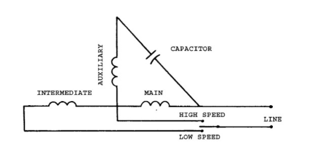
Start capacitor run capacitor or permanent capacitor. Single phase three phase wiring diagrams 1 phase 3 phase wring the star delta y δ 3 phase motor starting method by automatic star delta starter with. Collection of baldor single phase motor wiring diagram.
Also read about the speed torque characteristics of these motors along with its different types. Wondering how a capacitor can be used to start a single phase motor. Frequent stopstarts andor changing of the direction of rotation will damage the motors capacitors and winding.
Single phase motor wiring diagrams single voltage motor 208 230v ccw cw l2 l1 t1 t8 t4 t5 t1 t5 t4 t8 dual voltage motor 115v or 208 230v 208 230v or 460v low voltage high voltage ccw cw ccw cw l2 t1 t3 t8 t2 t4 t5 t1 t3 t5 t2 t4 t8 l1 t1 t3 t8 t2 t4 t5 t1 t3 t5 t2 t4 t8 l1 l2 dual voltage motor with manual overload mo 115v or 208 230v 208. This type of motor is designed to provide strong starting torque and strong running for applications such as large water pumps. Three phase motors with single phase frequency inverter should be used for frequent onoff switching.
The above diagram is a complete method of single phase motor wiring with circuit breaker and contactor. A wiring diagram is a streamlined traditional photographic depiction of an electrical circuit. Wiring diagram for single phase motor fresh pretty single phase.
If a single phase motor is single voltage or if either winding is intended for only one voltage the terminal marking shall be determined as follows.
Single Phase Motor Diagram Wiring Diagrams
.png)
 Electric Motors Connection Diagrams Neri Motori S R L
 Single Phase Capacitor Motor Diagrams Wiring Diagram

 Single Phase Capacitor Motor Diagrams Wiring Diagram
 Single Phase Electric Motor Wiring Diagram Wiring Diagrams Img
 Wiring Diagram 2 Speed Single Phase Motor Catalogue Of Schemas
 Wiring Diagram Ac Motor Single Phase Wiring Diagrams Sign
 Single Phase Capacitor Motor Wiring Diagram Wiring Diagram


 Electric Motor Single Phase Wiring The Best Place To Get

 Baldor Motor Connection Diagram Group Electrical Schemes

 Single Phase Capacitor Start Motor Wiring Wiring Diagram

 Motor Wiring Installation Tips Electrical Construction
 Ac Motor Control Circuits Ac Electric Circuits Worksheets
 Single Phase Motor Winding Connection Diagram Wiring

 Single Phase Motor Reverse And Forward Connection By Two Magnetic Contactor
 Baldor Motor Connection Diagram Group Electrical Schemes
 Motor Connections Diagrams Wiring Diagram Images Gallery
 Single Phase Induction Motors Electric Motor
 Wiring Diagram For Low Voltage Motor Wiring Diagram
0 Response to "Single Phase Motor Connection Diagram"
Post a Comment