Logical Vs Physical Network Diagram
With all of the devices and the connections between them. On the other hand a physical dfd shows how the system will be implemented.
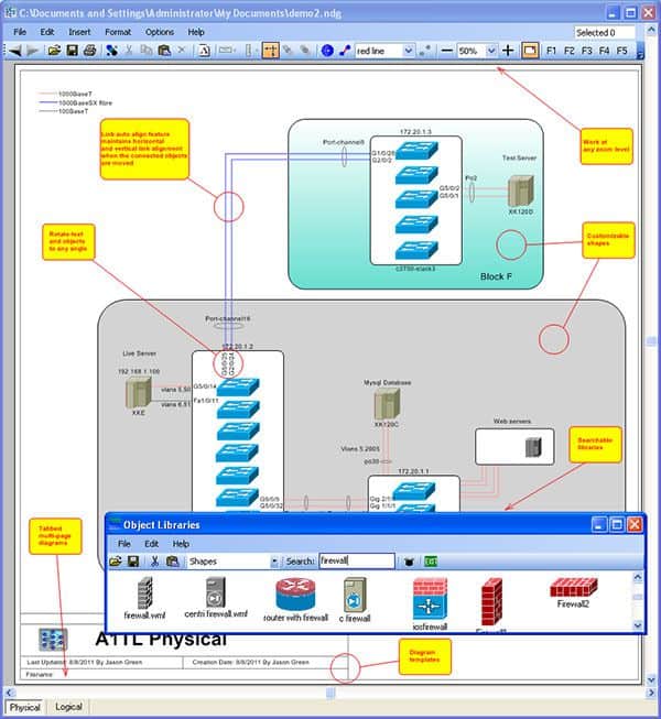
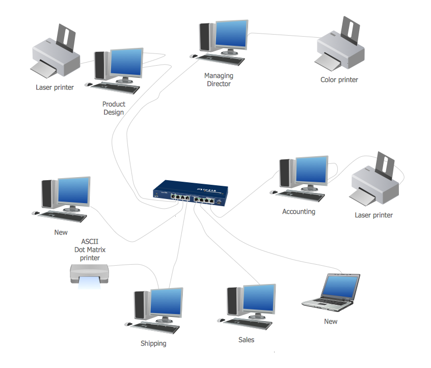
 Physical Diagrams Wiring Diagram
So while any data flow diagram maps out the flow of information for a process or system the logical diagram provides the what and the physical provides the how.

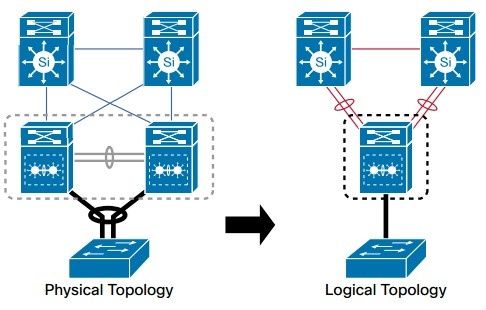
Logical vs physical network diagram. A logical dfd focuses on the business and how the business operates. Logical topology shows the temperament of the courses the way signals move from node to node. A physical network diagram illustrates the interconnection of the devices in the network with wires and cables.
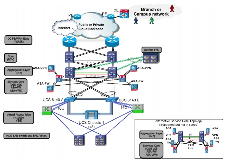
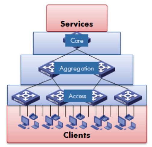
Most strong network designs require a sophisticated yet robust physical network diagram and a sensible logical network diagram. A physical topology is how they are actually interconnected with wires and cables. It describes the business events that take place and the data required and produced by each event.
Troubleshootingif service is out somewhere between two ip addresses you can use a logical network diagram to quickly rule out an issue caused by a firewall. Within the osi model of networking logical diagrams are referred to as l2. In terms of arithmetic the physical topology of a network is the real arithmetical arrangement of workstations.
While physical network diagrams are important logical diagrams make network management easier in the following ways. L2 devices such as switches are not depicted in an l3 or logical network diagram. A physical network diagram shows the physical connections of network components while a logical one shows how they relate and communicate with each other.
For example in a shared ethernet network that. As the information contained within logical network diagrams corresponds to the l3 layer 3 of the osi model. This network allows up to 254 hosts to be connected directly to it without the need of any routing.
Data flow diagrams dfds are categorized as either logical or physical. A logical topology is how devices appear connected to the user. A logical dfd focuses on the business and business activities while a physical dfd looks at how a system is implemented.
In most cases the logical network is a simple class c network such as 19216800 with the default subnetmask of 2552552550. A physical network diagram will ideally show the network topology exactly as it is. Physical vs logical topology.
In contrast the logical network diagram shows how they communicate with each other over physical connectivitys. A logical network layout clearly shows the ip addresses associated with each part of the network. The potentials of the network access devices and media decides the physical topology of a network.
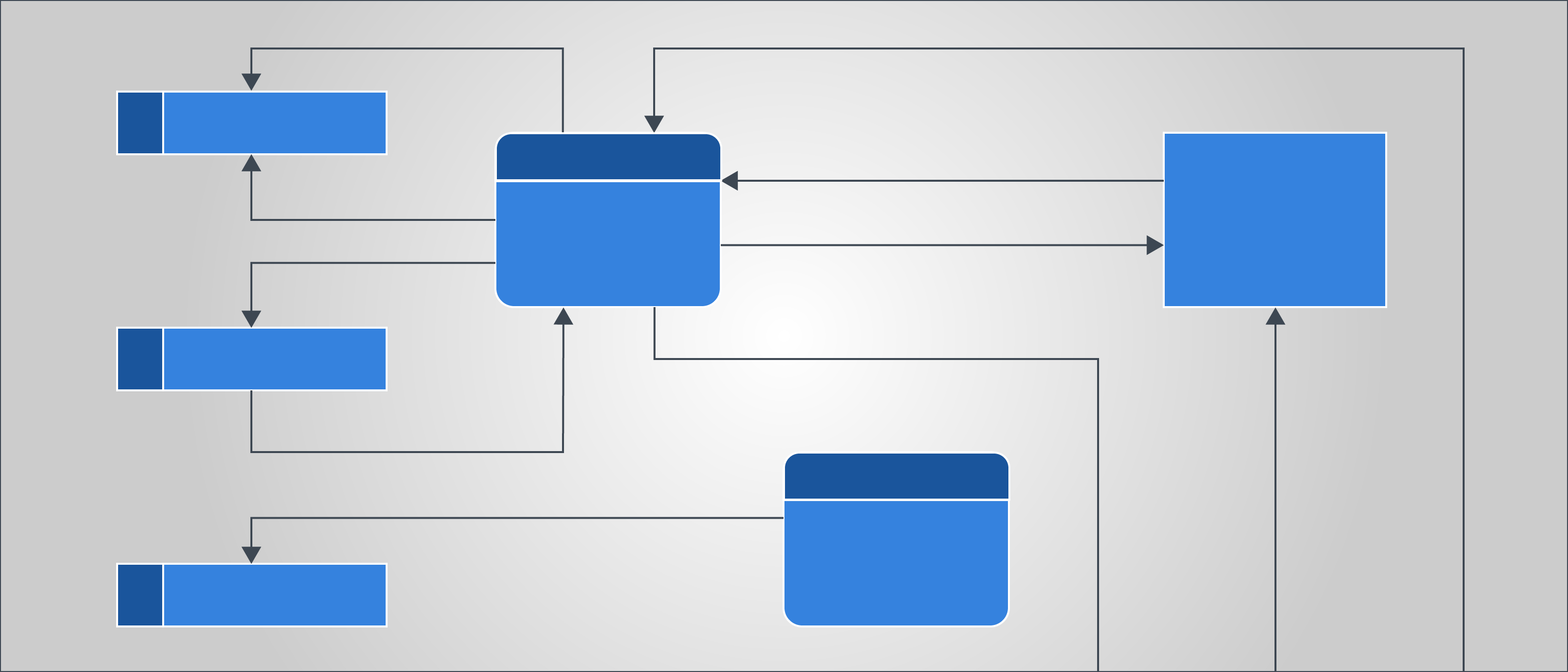 Data Flow Diagram Symbols Types And Tips Lucidchart
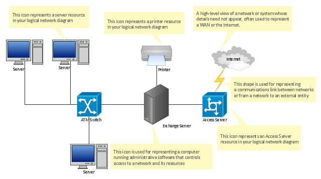
 Logical Network Diagram
 09 Data Link Layer Logical Vs Physical Topologies Part 4
60 Experienced Logical Diagrams
 Network Topologies Logical Vs Physical Aruba Blogs
 Logical Network Diagram Png On Networkdiagram Attachment
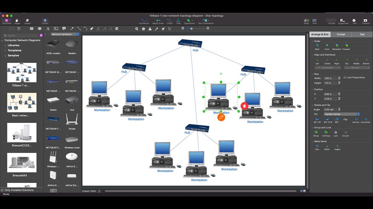 How To Create Network Topology Diagram
 Logical And Physical Address In Operating System Geeksforgeeks
 Logical Network Topology Diagram Physical Topology
 Troubleshooting Physical And Logical Topologies Bel S Blog
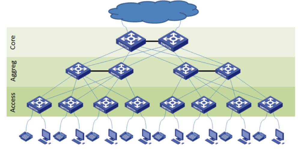
 Calix Ethernet Access Networks Engineering Planning Guide
 Physical Diagrams Wiring Diagram
 Shows An Example That Explains The Relationship Between

 Physical Bus Diagram Wiring Diagrams
 Logical Network Design Essay Help Nttermpaperwdik
 Physical Network Diagrams Wiring Diagram T1
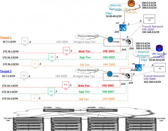
 Network Diagram Software Physical Network Diagram Logical
 Network Topologies Logical Vs Physical Aruba Blogs
 Based On What You Know From The Scenario Explain
 Network Topology 6 Network Topologies Explained Including
0 Response to "Logical Vs Physical Network Diagram"
Post a Comment