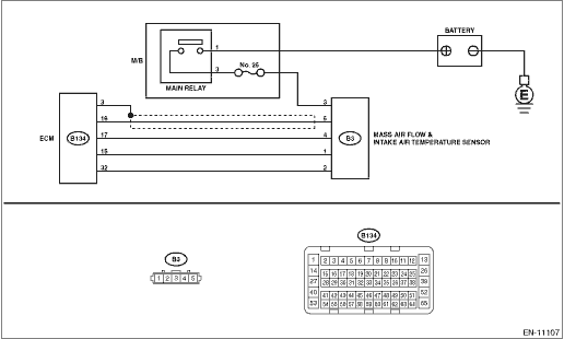
Mass Air Flow Sensor Wiring Diagram
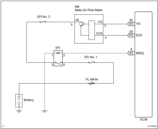
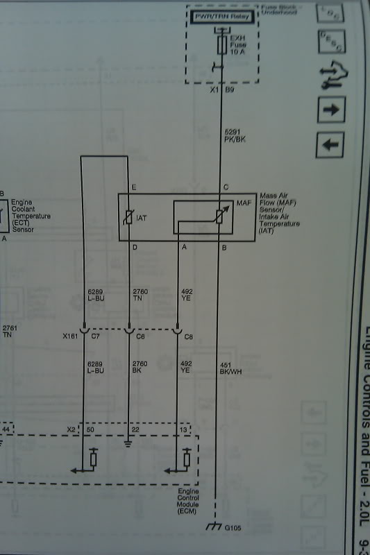
Its job is to keep track of the amount of air coming in through the air filter so that the ecu can adjust the amount of fuel getting into the engine. The following schematic shows a typical circuit diagram of the mass air flow maf sensor system.

Maf sensor wiring diagram 19971998 1999 ford 46l 54l.
Mass air flow sensor wiring diagram. If the specified value is not obtained check the wires of the mass air flow maf sensor. If the maf isnt working properly. The mass air flow sensor is often the likely culprit if your car isnt running as it should.
If the specified value is obtained but dtc memory has a dtc concerning mass air flow maf sensor check the voltage supply of the mass air flow maf sensor. Please be sure to leave positive feedback as this is the only way i receive credit for my work and time. Maf sensor gets power from the pcm power relay red wire.
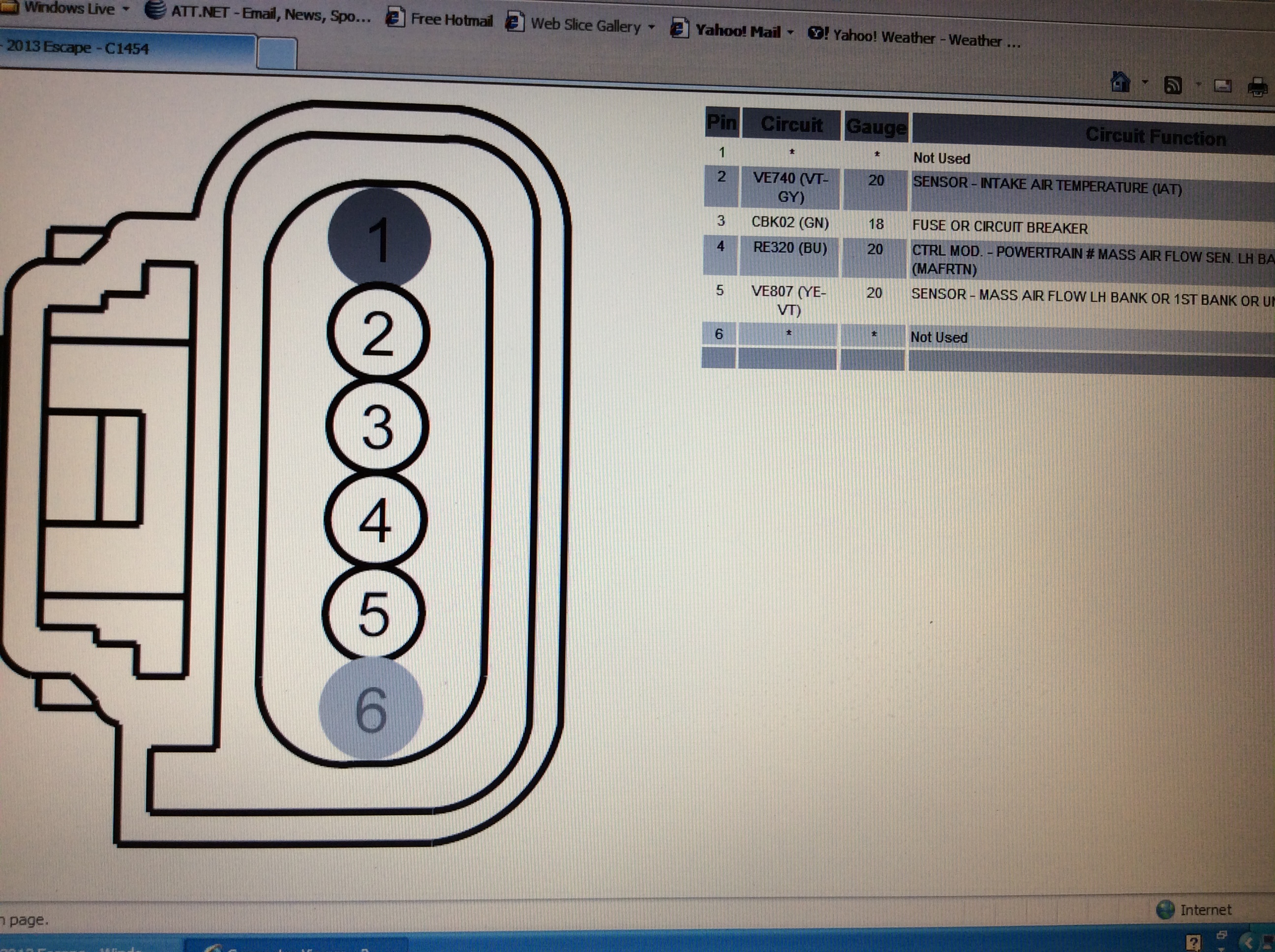
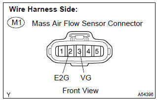
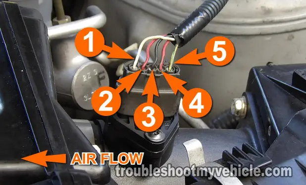
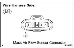
Mass air flow sensor wiring schematic. Autozone repair guide for your engine performance emission controls connector pin identification mass air flow maf sensor connector. It can be seen in the wiring diagram above.
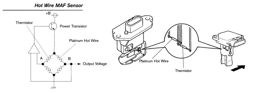
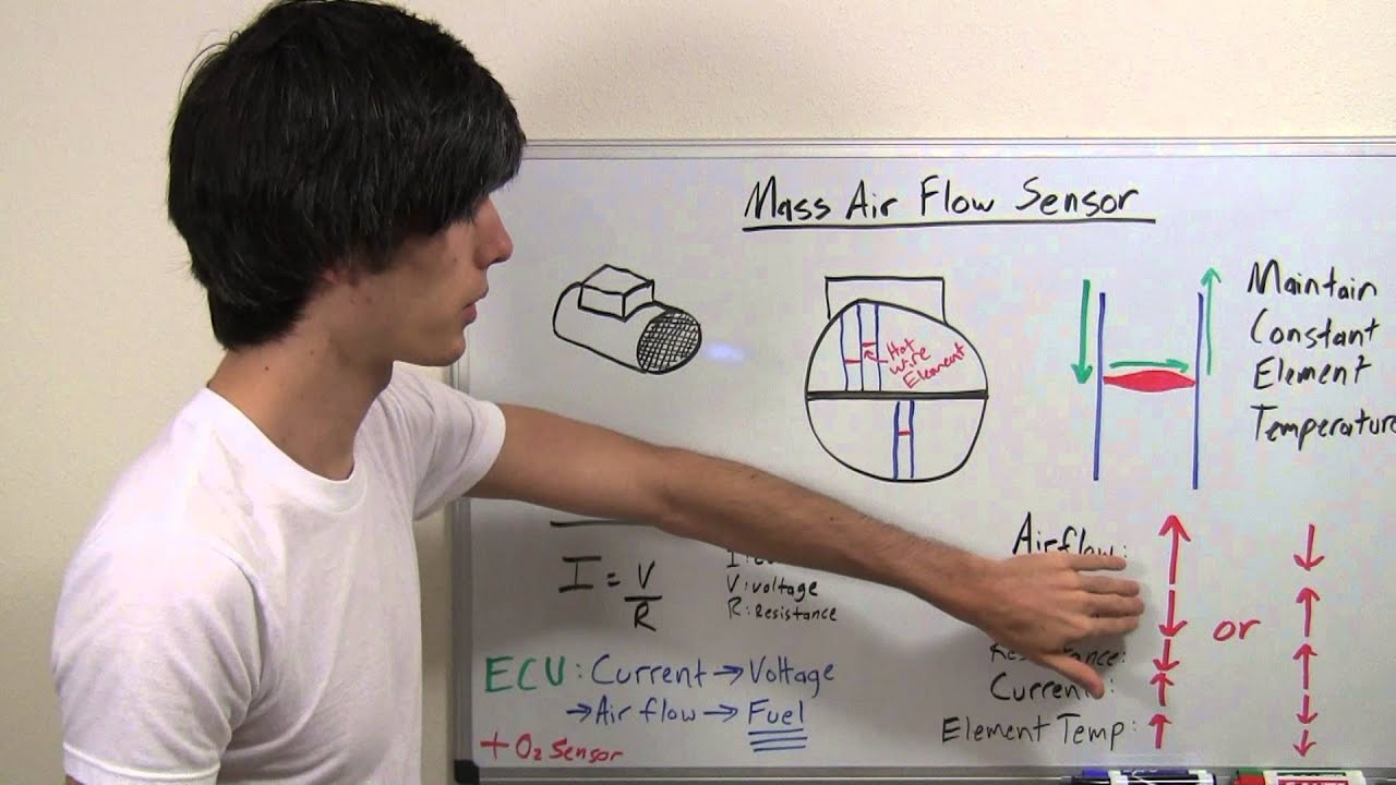
The primary components of the maf sensor are thermistor a platinum hot wire and an electronic control circuit. The lt blured wire outputs the maf signal to the pcm. The mass air flow sensors converts the amount of air drawn into the engine into a voltage signal.
F150 f250 f350 mustang crown victoria. If the maf is bad either because its not producing a signal or producing an erratic one the cars idle will return to normal and the car will seem to run fine. Shouldnt the mass air flow sensor dictate the voltage going out to the ecm.
The most common way to test the 5 wire vw mass air flow maf sensor is just to unplug it with the engine running. Hi there pin 5 the yellow wire with blue tracer mark is the intake temperature sensor input wire off the mass air flow sensor. My mass air flow sensor on an 88 camaro 28 reads 5 volt reference between signal and ground while running and unplugged on the ecm side at idle.
Learn how this device is connected to the ecm and vehicle electronics in general. The maf or mass air flow sensor is a main input to the ecm or engine computer form air intake temperature and flow. While plugged in there is erratic non detectable voltage onoff onoff.
 How To Test A Mass Air Flow Maf Sensor Without A Wiring Diagram

 Chevy Maf Sensor Wiring Diagram Wiring Diagrams Folder
 3 Wire To 5 Wire Maf Wiring Diagram Ls1tech Camaro And
 Toyota Maf Sensor Voltage
 2 7 Chrysler Maf Sensor Wiring List Of Wiring Diagrams

 Nissan 240sx Fuel Level Sensor Wiring Pinout Wiring
 Part 1 How To Test The Maf Sensor 2002 2003 3 5l Maxima
Colors Of The Mass Air Flow Sensor Connector Wires Ford
 Gm Mass Air Flow Sensor Wiring Wiring Diagram
 Pin On Charts
 Mass Air Flow Wiring Diagram 2009 Ss Chevy Hhr Network
 300zx Headlight Wiring Diagram Wiring Diagrams Folder
 Photo Sensor Wiring Diagram Help And Forum These Should Be

 F150 Maf Wiring Diagram Today Wiring Schematic Diagram
 Mass Air Flow Sensor Hot Wire Explained
 Delphi Mass Air Flow Sensor Wiring Diagram For Trailer


0 Response to "Mass Air Flow Sensor Wiring Diagram"
Post a Comment