Understanding Hvac Wiring Diagram
Use our menu to the right to find helpful articles such as thermostat wiring diagrams low voltage circuits for hvac how to wire an air conditioner for control control board troubleshooting and thermostat troubleshooting. It lists the circuit connections and electrical wiring for the system.

A wiring diagram is used to represent how the circuit generally appears.

Understanding hvac wiring diagram. Types of wiring diagrams there are three basic types of wiring diagrams used in the hvacr industrytoday. In this article i am going to explain the function and wiring of the most common home climate control thermostats. Wiring diagrams for hvac systems and other complicated electrical systems come in two major variations schematic diagrams and ladder diagrams.
The first and most common is the ladder diagram so called because it looks like the symbols that are used to represent the components in the system have been placed on the rungs of a ladder. Electrical wiring diagrams for air conditioning systems part one in article electrical rules and calculations for air conditioning systems part one which was the first article in our new course hvac 2. Thermostat terminal designations explanations.
The ladder diagram is one of the easier ones to read. We walk through some of the basics and most common symbols associated with reading an air conditioner wiring schematic or diagram. This information is designed to help you understand the function of the thermostat to assist you when installing a new one or replacing or up grading an old one.
From this point forward ladder dia. The first and most common is the ladder diagram. There are three basic types of wiring diagrams used in the hvacr industry today.
Of the two types of diagrams the ladder types are. To help illustrate the differences between wiring diagrams and schematics a basic control circuit will first be explained as a schematic and then shown as a wiring diagram. Read all the tech tips take the quizzes and find our handy.
Because it explains electrical circuits the diagram looks like a ladder which is where the name comes from. From this point forward ladder diagrams will be referred to as schematic diagrams or schematics the second type of diagram is the line diagram. Understanding how different hvac equipment operates in a certain hvac system.
 Air Conditioner Control Thermostat Wiring Diagram Hvac
 Hvac Air Handler Wiring Diagram Inspecting The System For


Residential Thermostat With Remote Sensor Wiring Schematic
 Electrical Hvac Wiring Wiring Diagram
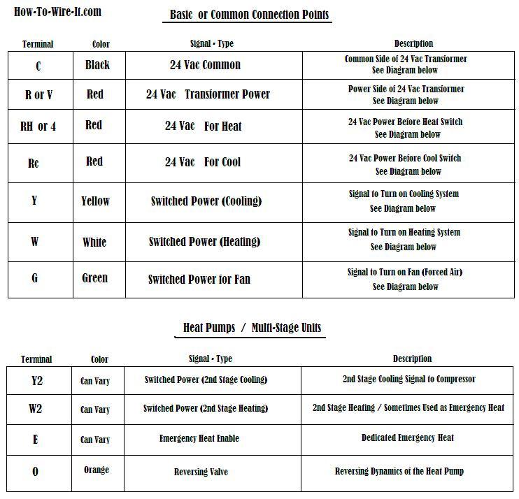
 Thermostat Signals And Wiring


 Ac Hvac Wiring Catalogue Of Schemas
 Wire A Thermostat
![]() Control Circuits For Air Conditioning Heating Hvac
Control Circuits For Air Conditioning Heating Hvac
 Hvac Diagrams Schematics Wiring Diagrams Folder
 Electrical Wiring Diagrams For Air Conditioning Systems
 Hvac Wiring Diagrams Pdf Engine Mechanical Components
 Hvac Unit Wiring Diagram Simple Diagrams Mini Split Air
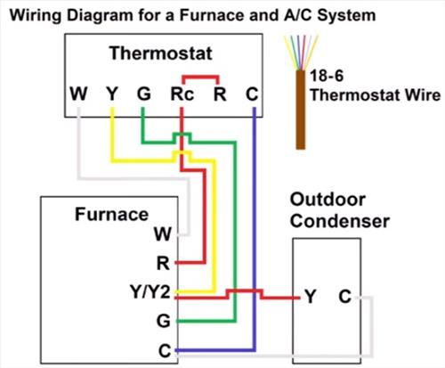
 Thermostat Wiring Explained
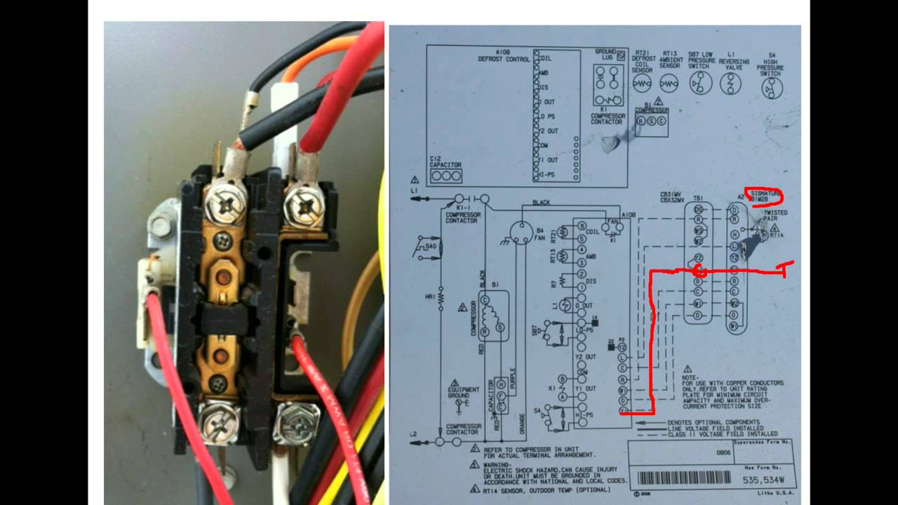 Hvac Training Understanding Schematics Contactors 2


 Hvac Unit Wiring Diagram Simple Diagrams Mini Split Air

0 Response to "Understanding Hvac Wiring Diagram"
Post a Comment