In A Sequence Diagram A Lifeline Is Identified By An Line
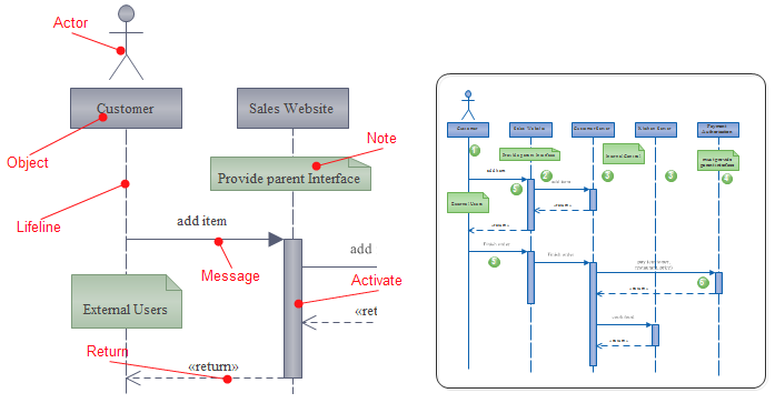
The head is located on top of a vertical dashed line called the stem which represents the timeline for the instance of the object. They represent the different objects or parts that interact with each other in the system during the sequence.
 Cite 2921 Study Guide 2012 13 Hall Instructor Hall At
In a sequence diagram an lifeline is identified by a line showing direction that runs between two objects false enables an object to derive one or more of its attributes from another object.
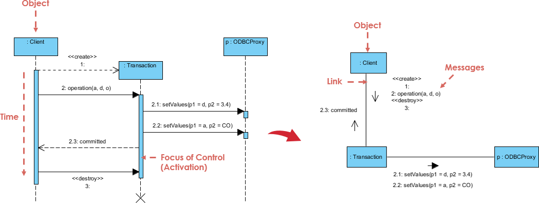
In a sequence diagram a lifeline is identified by an line. True false question 4 5 out of 5 points. Lifelines in sequence diagrams as the following figure illustrates a lifeline in a sequence diagram is displayed with its name and type in a rectangle which is called the head. Otherwise it goes from the top to.
True false question 3 5 out of 5 points in a sequence diagram an lifeline is identified by a line showing direction that runs between two objects. In a sequence diagram a lifeline is identified by an line. In a sequence diagram a message is identified by a narrow vertical shape that covers the lifeline.
Sequence diagram life lines represent different processes or objects that live simultaneouslylifelines represent only one interacting entityit is basically a vertical dashed line that represents existence of an object over a period of timethis line disappears when the object is destroyedas for example see the diagram below. The lifeline represents the existence of the object at a particular time. An object role in a sequence diagram is shown as a vertical dashed line called the lifeline.
Sequence diagram describes an interaction by focusing on the sequence of messages that are exchanged along with their corresponding occurrence specifications on the lifelines. In a sequence diagram a lifeline is identified by a line showing direction that runs between two objects. Uml sequence diagrams sequence diagram is the most common kind of interaction diagram which focuses on the message interchange between a number of lifelines.
No two lifeline notations should overlap each other. If the object is created or destroyed during the period of time shown on the diagram then its lifeline starts or stops at the appropriate point. A sequence diagram is made up of several of these lifeline notations that should be arranged horizontally across the top of the diagram.
Chapter 5 data and process modeling 26. In data and process modeling an model shows what the system must do regardless of how it will be implemented physically. In a sequence diagram a lifeline is identified by an line.
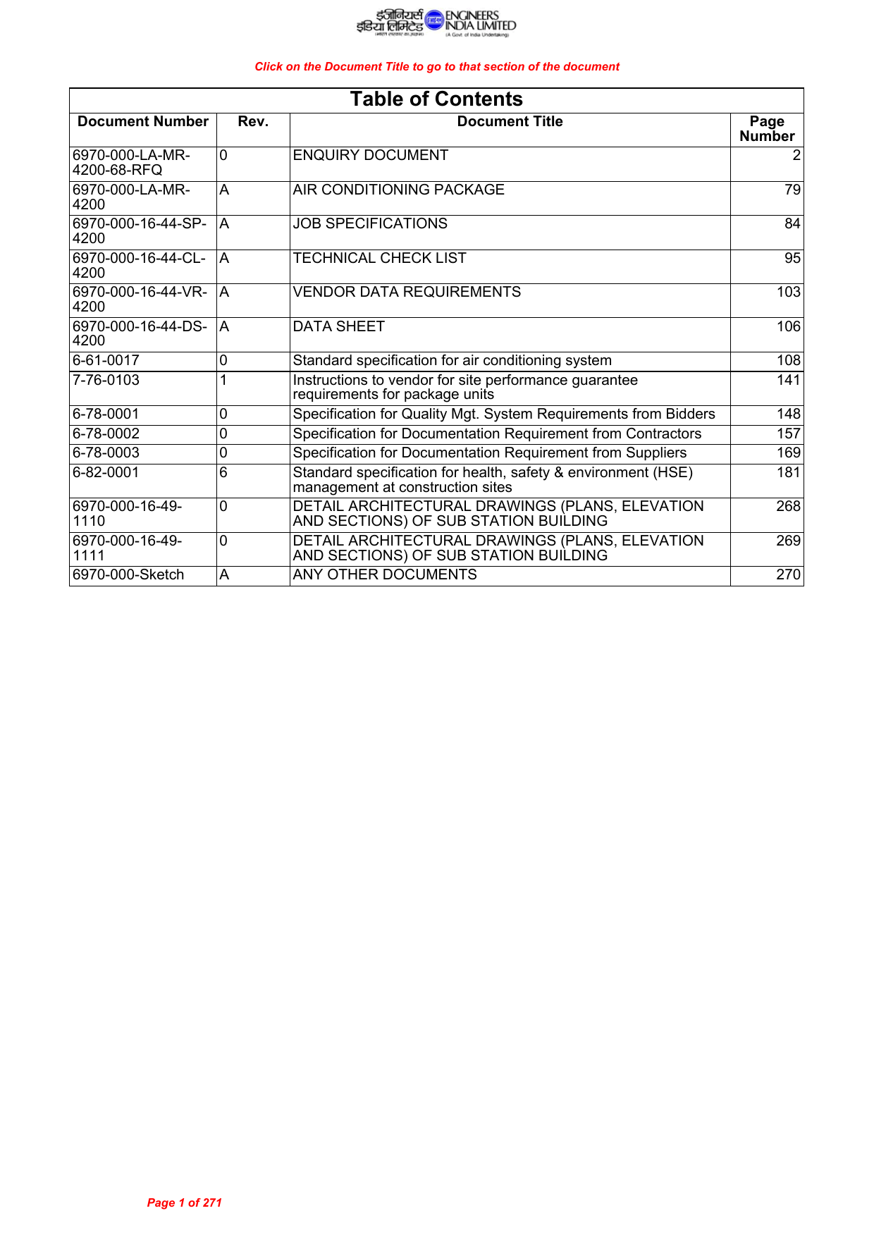 Table Of Contents Eil Tender Portal Manualzz Com
 Answer Selected Answer True Correct Answer Tru E Question 7
 Sequence Diagram In Uml Lecture Notes
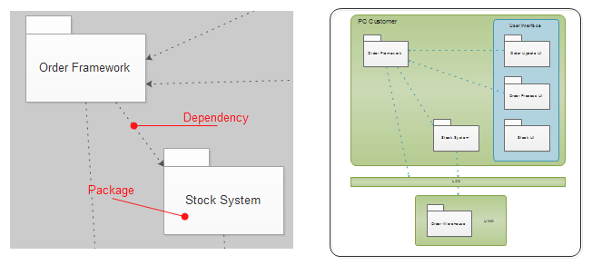 Different Uml Diagrams Purpose And Usage
Resolution Msc 267 85 Adopted On 4 December 2008 Adoption
 Midterm Week 5 Question 1 4 Out Of 4 Points In A
 Sequence Diagram In Uml Lecture Notes
P C E Co Cond E Onvey Ition Ca3 Yance Ass 3 E Sys Essm
Emergency Medical Services Authority July 23 2018 Ms Cathy
Cellular Automata As Simple Self Organizing Systems
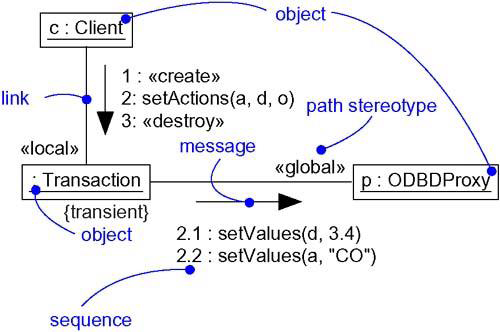
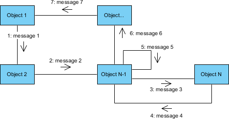
 What Is Communication Diagram
What Is Communication Diagram

 Blog Hope Mohr Dance

 Cis210 Week 5 Midterm Exam New By Grgsgsss Issuu
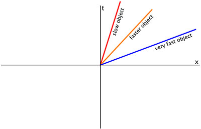 World Line Wikipedia
 Uml Modeling And Profiling Lab Advanced Software
Released Under Rti Dtmr
Ccu Conference Room Gloria B Nelson Public Service
 Different Uml Diagrams Purpose And Usage
 Software Engineering 2 Process Ppt Download
 What Is Communication Diagram
 American Gut An Open Platform For Citizen Science

 Cis 210 Week 5 Midterm Exam Strayer New By Alma Johnson
Verizon California Inc
0 Response to "In A Sequence Diagram A Lifeline Is Identified By An Line"
Post a Comment