Chill Water System Diagram
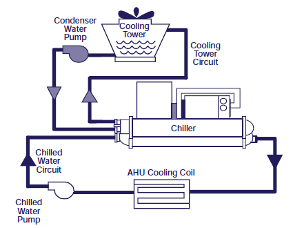
It is the condenser barrel where the refrigerant is condensed and sent back to the evaporator barrel to remove the heat. Supply temperature control strategies may be used on either constant or variable flow systems.
 Chilled Water System Water Chiller Others
The chilled water supply temperature is usually controlled by the chiller.
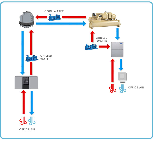
Chill water system diagram. Covering chillers pump sets ahus risers primary and secondary systems cooling towers and bypass lines. The refrigeration cycle step by step chiller diagram. 1 pipe systems a 1 pipe water distribution system is a system that has a one main pipe looping around the building and then returning.
The evaporator of the chiller is where the chilled water is generated. The chilled water leaves the evaporator at around 6c 428f and is pushed around the building by the chilled water pump. Most commonly supply water temperature is used as the sensed variable to permit control of chiller capacity to meet system load demand.
Increases system head and energy consumption insufficient space provided at the pump suction to enable satisfactory performance pump pitfalls provide flooded suction to condenser water pumps cooling tower sump should be at least 500 mm above the top of the pump volute be aware of access requirements as heights increase. Ily chilled water and condenser water system piping system design it is important to understand the evolution from 1 pipe into the other three systems all of which are used for heating as well as cooling. The process is in reverse in the condenser barrel.
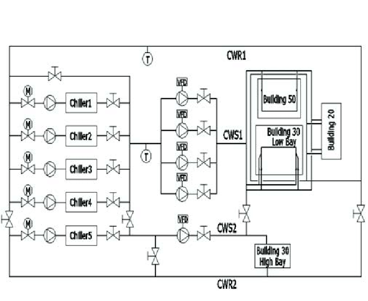
The water absorbs heat from the refrigerant and allows it to condense. Per chiller system load 500 tons 1760kw 1500 tons 5280kw primary secondary bypass flow 3000gpm 189 ls 3000gpm 189 ls 0gpm 0 ls delta t 12 of 67 oc 12 of 67 oc 100 ft 303 kpa head 100 load 100 sec flow 63 ls 1760 kw 56 ºf 133 ºc 56 ºf 189 ls at 133 ºc 133 ºc 50 ft 152 kpa head 0 gpm at 44 ºf 0 ls at 67 ºc. Chillers and cooling towers chilled water system basics.
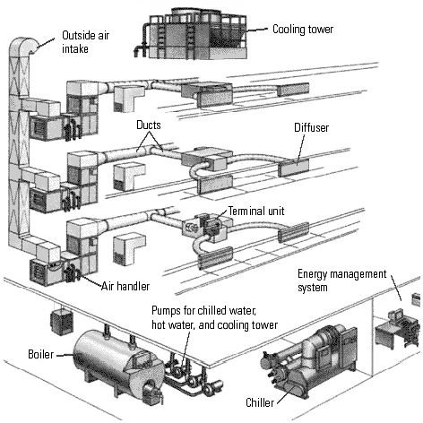
A chilled water system is a cooling system in which chilled water is circulated throughout the building or through cooling coils in an hvac system in order to provide space cooling. In the case of chillers heat is taken from the fluid being chilled and transferred to the ambient air. The refrigeration circuit is the most technical part of how a chiller worksthe refrigeration cycle uses the principles of thermodynamics to efficiently move heat from one area to another.
Chilled water schematic and condenser water schematic how to read and understand the engineering drawings with real world examples illustrations animations and video tutorial. The principal objectives of chilled water pumping system selection and design are to. The chilled water flows up the height of the building to each floor in pipes known as risers.
Chiller Application Guide
 Chilled Water System Download Scientific Diagram

 Applied Modeling Optimizes Plant Operation Modern Pumping
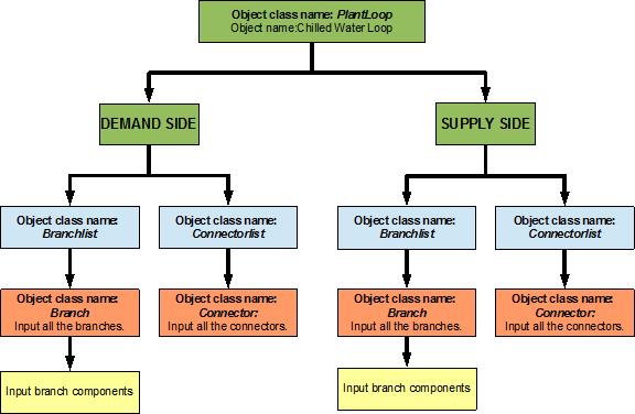
Chilled Water Cw Loop Plant Application Guide
 Implementing New Distributed Chilled Water Pumping System

 Chilled Water Central Air Conditioning Plants
 Evaluation Of The Design Of Chilled Water System Based On
 Retrocommissioning Findings Leveraging A Chilled Water
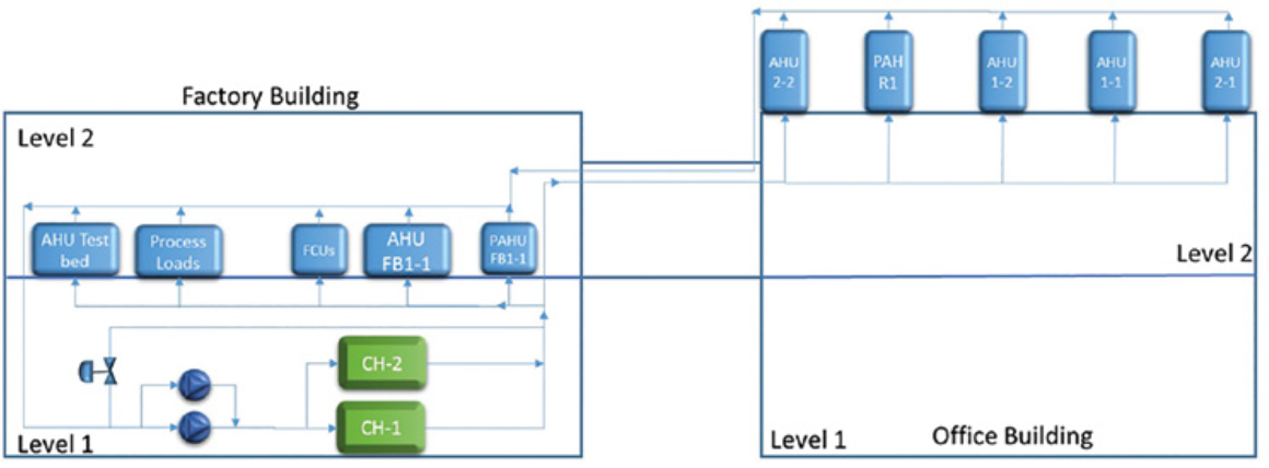
 Schematic Of A Typical Chilled Water System Download
 Chilled Water System Diagram Download Scientific Diagram
 Benefits Of Variable Primary Flow I P Version
 Chilled Water Central Air Conditioning Plants
 Hvac System Hvac Water Chillers Valves And Pumps
 Schematic Of A Typical Chilled Water System Download
 Schematic Diagram Of Uc Merced Chilled Water System

 Schematic Of A Typical Chilled Water System Download
 Performance Enhancement Of A Complex Chilled Water System
 35 Info Flow Diagram Chilled Water System Pdf Doc Download
 Schematic Diagram Of Uc Merced Chilled Water System
 The Hvac System Diagram From Peide Hvacaqua Com
 Dynamic Modeling And Self Optimizing Operation Of Chilled
0 Response to "Chill Water System Diagram"
Post a Comment