3 Way Mixing Valve Piping Diagram
V5013bcf approximate dimensions in inches millimeters. In both scenarios the valves are.
 4 Way Mixing Valve Piping Diagram Wiring Diagram Bookmark
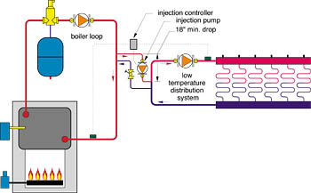
And hf friction loss in piping between valve and pump in feet of water.
3 way mixing valve piping diagram. Dismantle and clean hoses taps showerheads and thermostatic mixing valves minimum once a year. Check that inlet and outlet of 2 way valves are correct. Posted on november 30 2014 by admin.
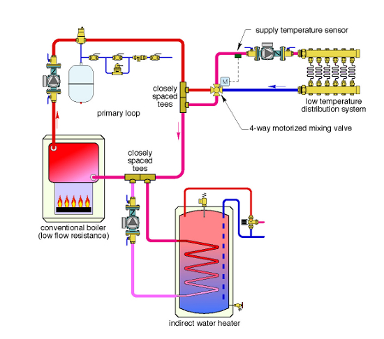
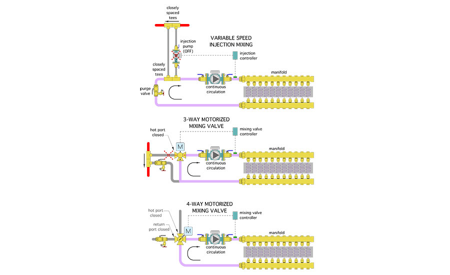
Model descriptions and body specifications. The valve body can install in any position and orientation. 2way3way4 way mixing valves to achieve outdoor mixing reset the position of a 2 3 or 4 way valve is modulated based on the relationship between outdoor temperature and supply water temperature reset ratioby modulating the valvea percentage of the hot water from the boiler loop is mixed with the cooler return water from the system.
Lf high capacity systems. Thermostatic mixing valves must be as close as possible to the point of use. Lf next generation high low systems.
Clean male pipe threads with wire brush and rag. April 1 2003. If threads have been damaged.
Install the power connections over the supply port to ensure proper flow direction see figure 3. The flow through the coil is still controlled by the stem position of the mixing valve. There are two types of three way valves used in the hvac industry.
December 9 2010. Learn more about hvac three way valves. Unfortunately not all of the information may be known to solve the static head pressure rating shpr.
Warranty and returns policy. Thermostatic mixing valves must allow easy cleaning and disinfection operation. Valve given an appropriate mixing valve piping arrangement.
Mixing valves and diverting valves. V5013bcf three way mixing and diverting valves 3 60 21294 table 1. Thermostatic mixing valves must have integrated check valves.
V5013bc flanged body dimensions. 3 way mixing valve piping diagram. Three way mixing valve installation guide 3 installation refer to the following installation instructions to properly install the uponor three way mixing valve.
Check that the a b and ab ports of three way valves are piped correctly. Current and obsolete manuals. A mixing valve can also be used in a bypass application to control the flow through the coil by placing the valve downstream of the coil.
The location of the three way valve will not affect the operation of the system. It can also quickly destroy a galvanized vent connector pipe. Blow out all piping and thoroughly clean before valve installation.
This device may be another three way mixing valve or one of several available preset thermostatic. Sidearm heaters 4 mixing 3 way valves are piped with the ab port common connected to return line and diverting system plumbing 7 1 10 typical three port control valve used in a mixing application. Flow direction arrows must be correct.
Lf thermostatic master mixers single valves lf thermostatic hl master mixers single valve. One way to solve this problem is to install a second mixing device as shown in figure 4. The dos and donts of three way thermostatic valves john siegenthaler pe.
 How To Video Installing Valves Featuring Push To Connect
 Piping Diagram 3 Way Valve Wiring Diagram
 Piping Diagram For Mixing Valves Wiring Diagram
 4 Way Mixing Valve Piping Diagram Wiring Diagram
 Mixing Valve Piping Diagram Schematics Online
 Mixing Valve Piping Diagram Schematics Online


 Piping Diagram 3 Way Valve Technical Diagrams
 4 Way Mixing Valve Piping Diagram Machine Learning


 4 Way Mixing Valve Piping Diagram Wiring Diagram
 Hvac System Piping 3 Way Mixing Valve 1 In
 Mixing Valve An Overview Sciencedirect Topics
 3 Way Mixing Valve Piping Diagram Wiring Diagram Schematics
 3 Way Zone Valve Piping Diagram Group Electrical Schemes
 4 Way Mixing Valve Piping Diagram Wiring Diagram
.jpg) 3 Way Valve Piping Diagram Wiring Diagram
3 Way Valve Piping Diagram Wiring Diagram

 Piping Diagram Valves Etc Structure Wiring Diagram
 4 Way Mixing Valve Piping Diagram Wiring Diagram
 Piping Diagram For Mixing Valves Group Electrical Schemes
 3 Way Mixing Valve Piping Diagram Wiring Diagram
0 Response to "3 Way Mixing Valve Piping Diagram"
Post a Comment