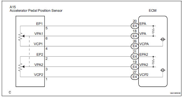
Accelerator Pedal Position Sensor Wiring Diagram
As the throttle valve opens the output increases so that at wide open throttle the output voltage should be approximately 45 volts. How do you know if a throttle position sensor tps is bad.
At a closed throttle position the output of the tps is low approximately 05 volts.

Accelerator pedal position sensor wiring diagram. So you need to conduct some tests. The accelerator pedal assembly is not connected to the throttle plate via a cable like in the good ole days. A properly operating app sensor should display a linear sweep of the entire accelerator pedal range and should not exhibit any voltage drop or signal break.
We want to use an electronic throttle pedal for a cts on our driving simulators at work they are pretty inexpensive. Accelerator pedal position sensor. Of course some symptoms can tell you when a tps may be bad.
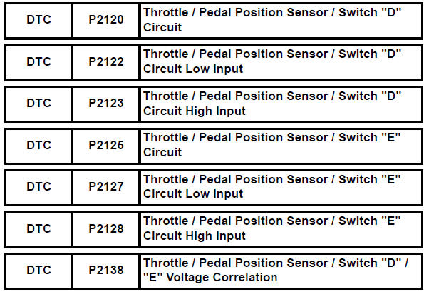
Dtc p2122104 throttlepedal position sensorswitch d circuit low input. But these symptoms may come from other bad sensors parts or components. Accelerator pedal position sensor wiring diagram see more about accelerator pedal position sensor wiring diagram accelerator pedal position sensor circuit diagram accelerator pedal position sensor wiring diagram ford accelerator pedal position sensor wiring diagram throttle position sensor wiring diagram.
As the throttle valve angle is changed accelerator pedal moved the output of the tps also changes. That the accelerator pedal assembly is made up of 3 individual position sensors. The tps connects to the throttle plate on the throttle body.
Each one has separate signal ground and 50 volt reference circuits. Each component ought to be set and connected with different parts in particular way. Wire harness or connector accelerator pedal rod assembly hv control ecu p2123 105.
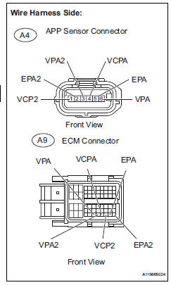
The accelerator pedal position sensor is inside the accelerator pedal assembly. Electronic throttle motor wires identification. Accelerator pedal position sensor wiring diagram accelerator pedal position sensor circuit diagram accelerator pedal position sensor wiring diagram ford focus accelerator pedal position sensor wiring diagram every electric structure is composed of various distinct parts.
This procedure is a mute point if you have the wiring diagram but often times you just need to actuate the electronic throttle to do a cleaning. However i cant seem to track down a wiring diagram for the pins at the pedal sensor. Wiring diagram inspection procedure 1 read value of handheld testeraccel pos 1 and 2 a connect the handheld tester to the dlc3.

 Throttle Position Sensor Tps Circuit Circuit Description The
 Gm Tps Wiring Wiring Diagram

 06 Sorento Tps Wiring Diagram Wiring Diagrams Folder
 Ford Tps Sensor Wiring Bookmark About Wiring Diagram
 Pin On Auto Electrical
 P2128 Accelerator Pedal Position Sensor 2 Circuit High
 06 Sorento Tps Wiring Diagram Wiring Diagrams Folder

Toyota Throttle Position Sensor All About Circuits
 Ford Electronic Pedal Wiring Wiring Diagram
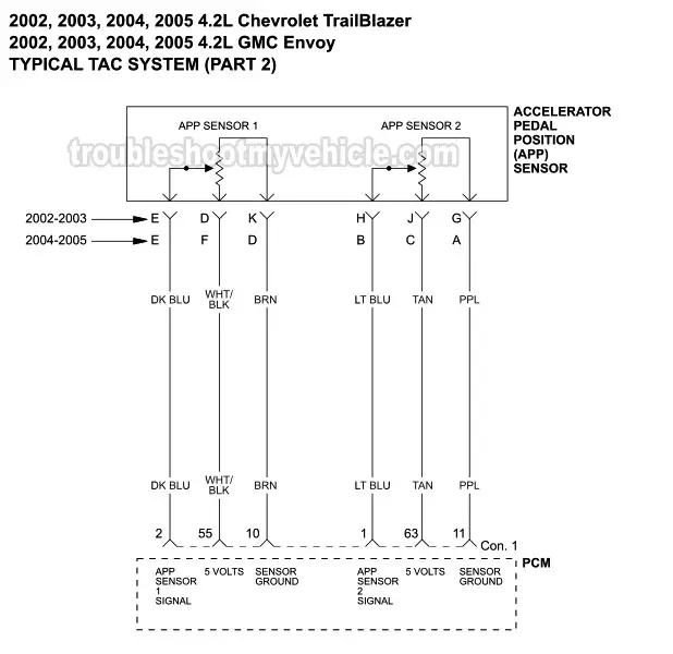 Wiring Schematics For 2003 Gmc Envoy Catalogue Of Schemas

Toyota Belta Wiring Diagram Schematics Online

 Wiring Diagram Dodge Throttle Position Sensor Wiring


 Wiring Diagram General Engine Diagrams Wiring Diagram K6
![]() Accelerator Pedal Position App Sensor Wiring Diagram
Accelerator Pedal Position App Sensor Wiring Diagram

0 Response to "Accelerator Pedal Position Sensor Wiring Diagram"
Post a Comment