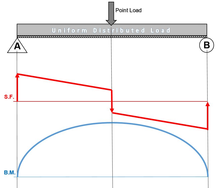
Draw The Shear Diagram For 0 X 14 Ft Of The Compound Beam
Knowing how to calculate and draw these diagrams are important for any engineer that deals with any type of structure because it is critical to know where large amounts of loads and bending are taking place on a beam so that you can make sure your structure can. 14 ft of the compound beam.
329 6 1 Draw The Shear And Moment Diagrams For The Shaft
Draw the shear and bending moment diagrams for the beam.
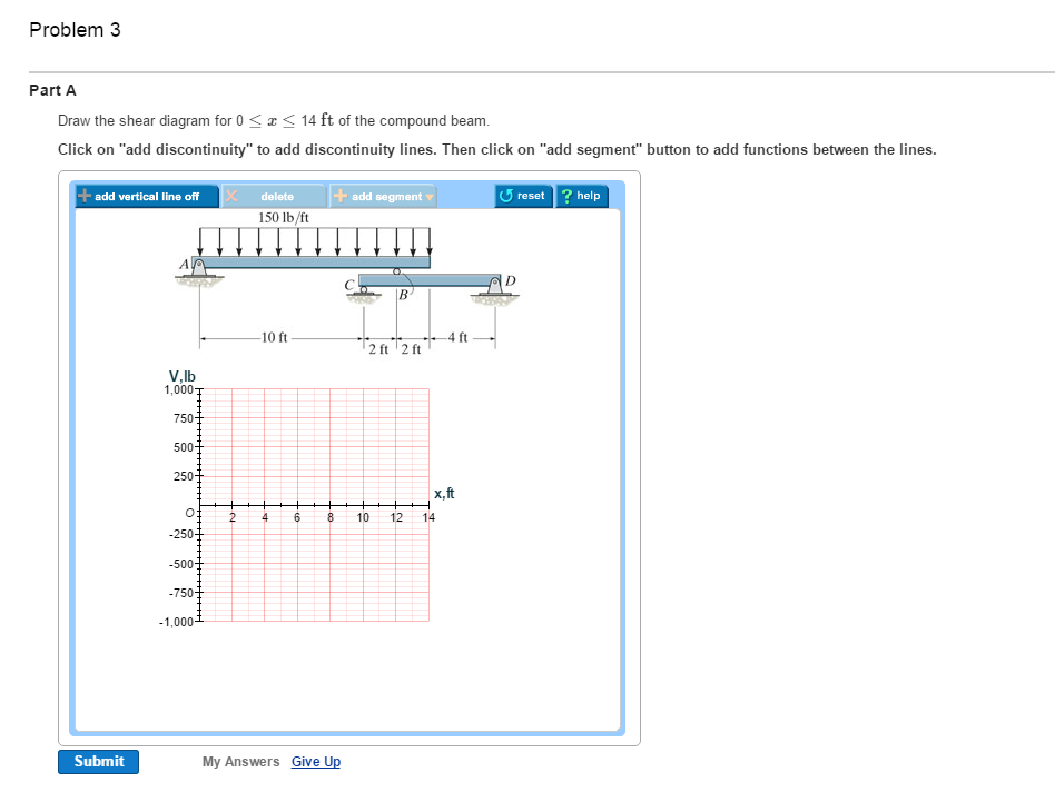
Draw the shear diagram for 0 x 14 ft of the compound beam. Shear and moment diagram example 2 mechanics of materials and statics duration. Sfd and bmd for cantilever beam problem 1 shear force and bending moment diagram duration. This beam calculator is designed to help you calculate and plot the bending moment diagram bmd shear force diagram sfd axial force diagram.
M 450x 4 0 v 1050 150x cf y 0 150x 4 v 450 0 m lb ft v lb 200 200 450 475 450 x x ans. Draw the shear diagram for 0. Part a draw the shear diagram for 0 x part b draw the bending moment diagram for 0 x 14 ft of the compound beam.
The shaft is supported by a smooth thrust bearing at a and a smooth journal bearing at b. Draw the shear and moment diagrams for the shaft. 100010 200 20 0 490 lb b y y m a a m 50x 490 v m v 490 v lb 980 x 510 m lbft 2401 200 fig a fig b 5 15.
Ft 150114 x2a 14 x 2 m 0. These instructions will help you to calculate and draw shear and bending moment diagram as well as draw the resulting deflection. D y 91875 1225 0 d y 30625 lb m d 0.
14 ft of the compound beam. B 875x 0 v 5875 150x6 lb c f y 0. The support at a is a thrust bearing and at b it is a journal bearing.
14 ft of the compound beam. A m 75x2 1050x 3200 ans 200 150x 4 x 4 2 m 0. B m 0 v 52100 150x6 lb c f y 0.
Calculate the reactions at the supports of a beam. This problem has been solved. Draw the shear diagram for 0.
A y 1225 2100 0 a y 875 lb. 875 150x v 0 0 x12 ft c f y 0. Draw the shear and moment diagrams for the beam and determine the shear and moment in the beam as functions of x where 4 ft x 10 ft.
Part c draw the shear diagram for member cbd 0 x 8 ft of the compound beam. Draw the shear and moment diagrams for the beam. Part d draw the bending moment diagram for member cbd 0 x 8 ft of the compound beam.
1225162 c y182 0 c y 91875 lb c f y 0. V 150114 x2 0 12 ftx 14 ft m 5875x 750x26 lb ft m 150xa x 2 m 0. Draw the shear and moment diagrams for the beam.
200 lb ft b x 4 ft 4 ft 150 lbft 6 ft 200 lb ft a ans.
329 6 1 Draw The Shear And Moment Diagrams For The Shaft
250 7500 0 2 V X N
Contents
329 6 1 Draw The Shear And Moment Diagrams For The Shaft
250 7500 0 2 V X N
Solution
Internal Loadings The Internal Torque Developed In Segments
Internal Loadings The Internal Torque Developed In Segments
![]() Ch06 07 Pure Bending Amp Transverse Shear
Ch06 07 Pure Bending Amp Transverse Shear
 Pdf Statics Note Statics Solution And Answer Syuqeri
Mechanics Of Materials Chapter 4 Shear And Moment In Beams
Internal Loadings The Internal Torque Developed In Segments
 Beam Reactions And Diagrams Strength Of Materials
Mechanics Of Materials Chapter 4 Shear And Moment In Beams
Book Solution Mechanics Of Materials Russell C Hibbeler
Mechanics Of Materials Chapter 4 Shear And Moment In Beams
329 6 1 Draw The Shear And Moment Diagrams For The Shaft
250 7500 0 2 V X N
Hibbeler Chapter 6 Part 1 463 486 Qxd
329 6 1 Draw The Shear And Moment Diagrams For The Shaft
Mechanics Of Materials Chapter 4 Shear And Moment In Beams
Solution
 Solved Draw The Shear Diagram For 0 X 14 Ft Of The Co
0 Response to "Draw The Shear Diagram For 0 X 14 Ft Of The Compound Beam"
Post a Comment