Water Treatment Process Diagram
Suspended particles get stuck to the chemicals to form floc. Secondary or biological treatment.

Oil industry process flow diagram.

Water treatment process diagram. Place the plastic funnel on the stand. With arsenic and uranium contamination concentrations are important. Oil refining hydrodesulphurization.
As already stated preliminary treatment involves the removal. Text in this example. They learn how to read a schematic diagram and relate the steps to a schematic.
Processes of waste water treatment. Activity kit 4 water treatment plant 7 1. Water treatment industry but each individual must adapt the results to fit their own practice.
As particles get stuck they become heavy and sink to the bottom of the chamber. The heavy particles floc settle to the bottom and the clear water moves to filtration. Browse process flow diagram templates and examples you can make with smartdraw.
Place another marked 120ml beaker under the funnel ready to collect the filtered water. Oil refining isomerization 1. Using the plastic funnel follow the steps to produce an individual filter for each group.
4 process with diagram 1. Drinking water treatment process flow diagram. Water treatment activity number label function description 67 treating waste water constructing understanding students engage in hands on process of cleaning up the water.
The usepa and the center for drinking water optimization shall not be liable for any direct indirect consequential or incidental damages resulting from the use of the wtp model. Water is placed in a closed tank or reservoir for disinfection to take place. Alum and other chemicals are added to the water at this stage.
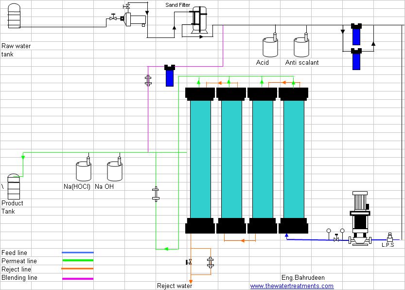
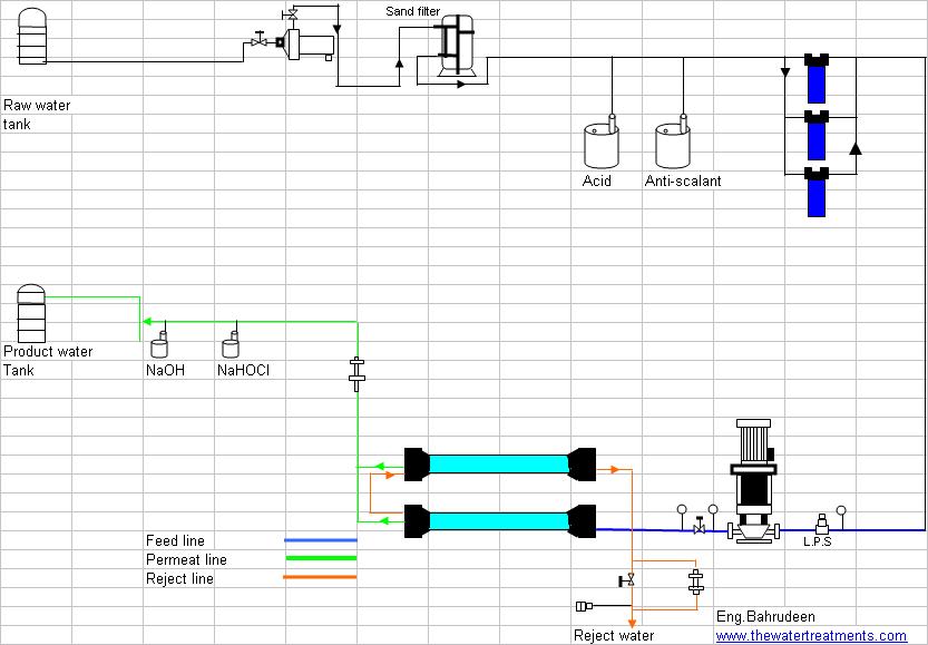
At 25 ppb as i can run a system at 40 gpm however at 120 ppb as i need to reduce it down to 10 gpm with the same system to increase contact time. Create process flow diagram examples like this template called drinking water treatment process flow diagram that you can easily edit and customize in minutes. Industrial water treatment systems process flow diagram.
Place cotton wool at the bottom of the funnel. A schematic represents another type of model. These are existing industrial water treatment systems they can be sized from 10 gpm to 250 gpm.
The diagram below shows a basic water treatment process for surface water. Primary treatment is aimed at the removal of fine suspended organic solids.


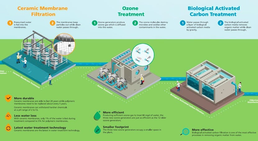 Pub Opens World S Largest Ceramic Membrane Water Treatment Plant
 Water Treatment Plant Diagram Of The Drinking Water


 Manx Utilities Water Treatment Works
 Industrial Wastewater Treatment Process Overview Jwc
 Pin On Life Plants Animals Nature
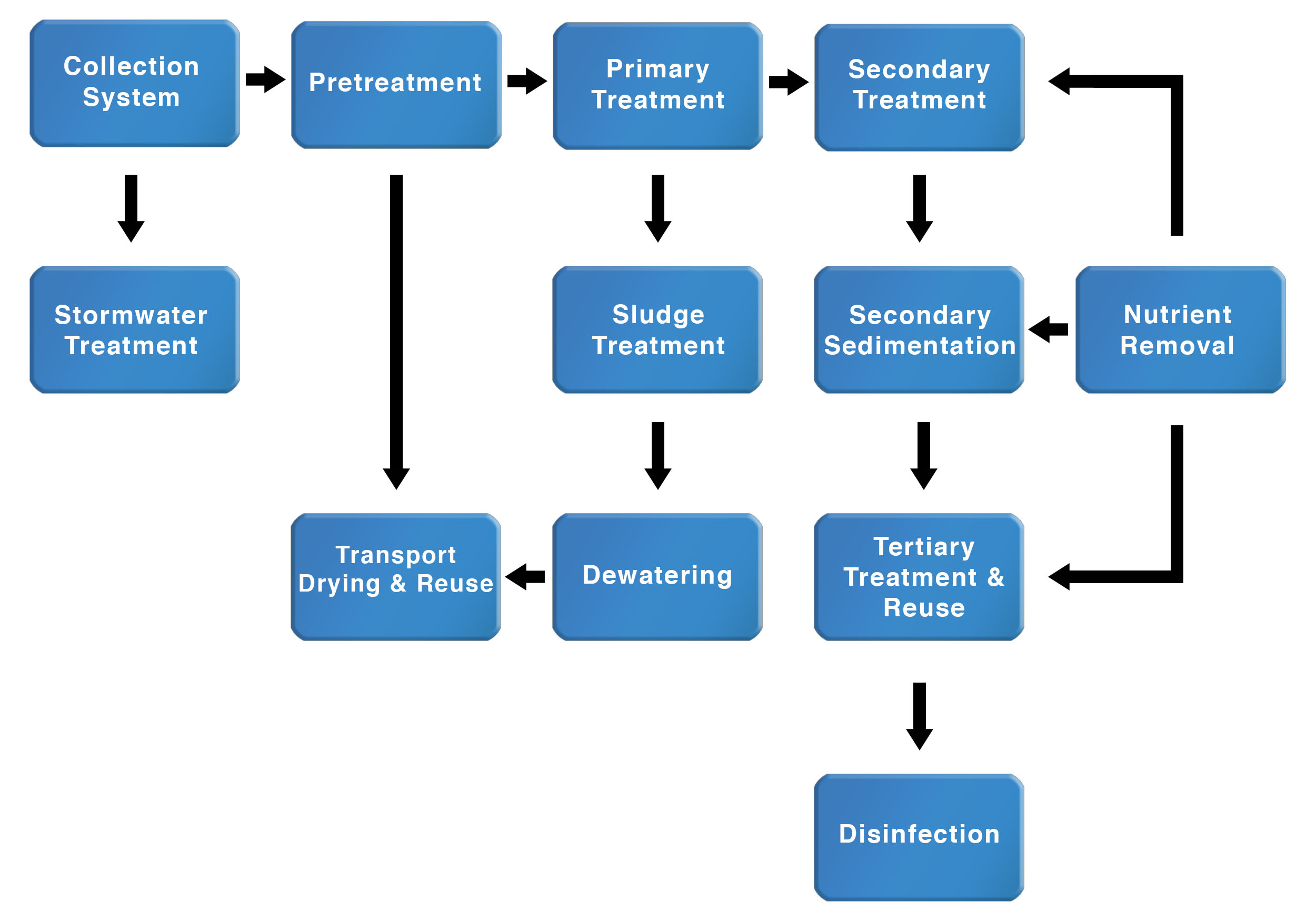 Diagram Of Water Treatment Wiring Diagrams Folder
 Water Treatment Plant An Overview Sciencedirect Topics
 Water Treatment Plant Diagram Of The Drinking Water
 The City Of Calgary Water Treatment Online Tour

 Water Treatment Schematic Diagram Wiring Diagram Bookmark
 Bakery Industry Flow Diagram For Bakery Waste Water
 Eastern Treatment Plant Melbourne Water
 Sewage Treatment Wikipedia
Water Treatment Engr 360 Water In Africa Technology
 Process Flow Diagram For Water Treatment Plant Wiring
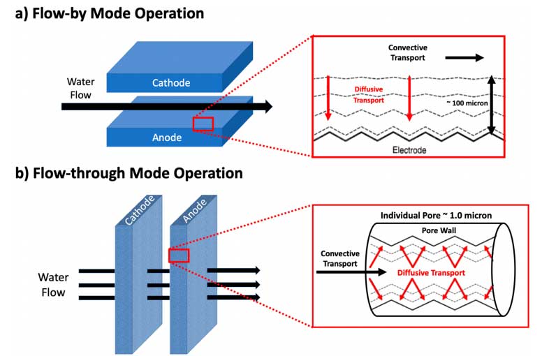 Uic Professor Looks To The Future Of Electrochemical Water
 Miex Water Purification Process Csiropedia
 Water Treatment Quality The Town Of Okotoks

 Schematic Diagram Of The Drinking Water Treatment Plant Pas
0 Response to "Water Treatment Process Diagram"
Post a Comment